

For a manufacturing plant with a 150 kW critical load, industrial UPS sizing must account for real power, apparent power, motor-starting kVA, nonlinear loads, and required battery autonomy rather than relying on steady-state kW alone. A three-phase online double-conversion UPS rated at approximately 250–300 kW is a reasonable preliminary design range, subject to verification of motor-starting profiles, load-step response, overload capability, ambient derating, and the actual critical-load boundary. Where large motors must start while operating on inverter power, a higher-rated UPS, a dedicated motor-starting strategy, or separation of motor loads from the UPS-backed bus may be necessary.
Industrial UPS Sizing: Engineering Comparison Matrix for a 150 kW Critical Load
The following comparison provides a preliminary selection framework for a three-phase industrial UPS. Final equipment selection requires a verified load schedule, motor-starting study, manufacturer-specific overload curves, and the required redundancy level.
| Design parameter | Preliminary design basis | Engineering verification requirement |
|---|---|---|
| Critical load | 150 kW | Confirm the maximum coincident demand, including auxiliaries |
| UPS topology | Online double-conversion, three-phase | Verify voltage regulation, transfer behavior, and dynamic response |
| Preliminary UPS power rating | 250–300 kW | Confirm kW and kVA limits independently |
| Power factor | Actual load PF; assess 0.90–1.00 as a screening range | Measure displacement PF and total power factor under operating conditions |
| Nominal system voltage | 380–415 V AC or 480 V AC, as applicable | Match local supply, load voltage, frequency, and grounding system |
| Motor-starting demand | Determined from starting current and duration | Verify inverter current limit, voltage dip, and overload duration |
| Load-step response | Based on the largest simultaneous load change | Obtain manufacturer test data for voltage deviation and recovery time |
| Battery autonomy | Defined by required ride-through and shutdown time | Calculate using the actual DC bus, battery discharge curves, temperature, and end-of-life criteria |
| Redundancy | N, N+1, or dual-bus architecture | Verify capacity remaining after the specified failure |
| Environmental rating | Based on the electrical room or plant location | Check ambient temperature, dust, humidity, vibration, altitude, and corrosion |
| Performance standard | IEC 62040-3 | Specify and verify the applicable UPS performance classification and test requirements |
| Safety standard | IEC 62040-1 and applicable local requirements | Verify equipment conformity, installation requirements, and jurisdiction-specific approvals |
IEC 62040-3 specifies UPS performance and test requirements, while IEC 62040-1 addresses UPS safety. Compliance with these standards does not, by itself, establish compliance with every local installation code or product certification requirement.
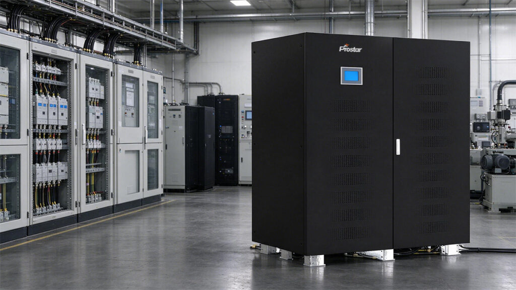
Industrial Online Double-Conversion vs. Standard Enterprise UPS
| Technical Parameter | Industrial-Grade 3-Phase Online UPS | Enterprise Data Center UPS | Engineering Impact on Manufacturing Loads |
| Inverter Overload Capacity | 150% for 10 min; 200% for 1 min; 1000% for 10 ms (fuse clearance) | 125% for 10 min; 150% for 1 min | Prevents trip during high motor-starting locked-rotor current (LRC) surges. |
| Input Power Factor (PF) & THDi | Active PFC > 0.99 PF; Input THDi < 3% at full load | Active PFC > 0.99 PF; Input THDi < 5% | Minimizes upstream generator sizing ratio and prevents transformer overheating. |
| Galvanic Isolation | Integrated heavy-duty inverter output isolation transformer (standard) | Transformerless (IGBT topologies, standard) | Prevents DC bus injection into loads; eliminates zero-sequence grounding loops. |
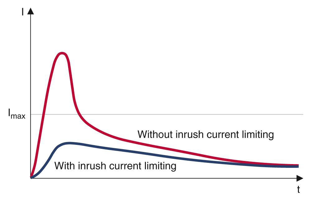
| Inrush Current Withstand | Built-in step-up transformer / bypass robust against 6–10× In surge | Limited to 2–3× In before transferring to bypass | Handles direct-on-line (DOL) motor starts and inductive transformer saturation. |
| Ingress Protection & Enclosure | NEMA 12 / IP54 (standard enclosure option with dust filters) | NEMA 1 / IP20 (standard computer room air handler environments) | Protects internal PCBs from conductive dust, moisture, and chemical airborne agents. |
| Operating Temperature Range | -10°C to +50°C (with de-rating above 40°C) | 0°C to +40°C (optimized for strict 20–25°C HVAC settings) | Ensures high reliability in harsh factory environments without dedicated HVAC. |
| Battery Compatibility | VRLA, NiCd (Nickel-Cadmium), LiFePO4 (Lithium Iron Phosphate) | VRLA, NMC/LFP Lithium-ion | NiCd provides high discharge rates and performance at extreme ambient temperatures. |
UPS Capacity for Motor Inrush, Overloads & Future Expansion
When sizing a 3-phase industrial ups for a manufacturing facility with high inductive and dynamic loads, engineers apply cumulative sizing multipliers rather than guessing a flat percentage.
To safely accommodate motor inrush currents, operational overloads, and future plant expansion, you should typically target a total system capacity that is 1.5× to 2.0× your baseline steady-state apparent power (Sbase ).
The breakdown of how to allocate capacity across these three key engineering parameters includes the following standards:
1. Motor Inrush Current Allowance
Direct-On-Line (DOL) induction motors draw 6× to 8× their Full Load Amperes (FLA) during startup. However, you do not need to oversize the entire UPS 6×, because doing so is cost-prohibitive. Instead, evaluate how motor starts interact with the UPS:
- Single Largest Motor Rule: Identify the single largest motor starting across the bus. If it starts DOL, calculate its peak apparent power ( Sstart ) and verify that it falls within the UPS inverter’s short-term overload envelope (e.g., 150% for 10 minutes or 200% for 1 minute).
- Multiplier Recommendation (kinrush): If motor starting is unmanaged (DOL), apply a 1.25× to 1.40× multiplier to your baseline apparent power to absorb voltage sags and prevent the UPS from transferring to static bypass. If Variable Frequency Drives (VFDs) or soft starters are used, this factor can be reduced to 1.05× to 1.10×.
2. Operational Overload & Harmonic Margin
Industrial environments experience non-linear harmonic currents, reactive power fluctuations (low lagging power factor of 0.80 or lower), and brief cyclic peak overloads from machinery.
- Crest Factor & Reactive Power: Standard industrial online double-conversion UPS units are designed to handle high crest factors (typically 3:1), but running close to maximum thermal limits reduces semiconductor lifespan.
- Multiplier Recommendation (koverload): Apply a 1.15× to 1.25× safety factor to account for power factor derating, harmonic heating in the inverter bridge, and transient operational spikes.
3. Future Load Expansion Margin
Manufacturing facilities frequently add automation lines, robotic cells, or auxiliary pumps over a 3- to 7-year capital expenditure lifecycle.
Standard industrial design practice dictates adding a 1.20× to 1.30× (20% to 30%) growth headroom buffer. This ensures the UPS operates at an optimal efficiency sweet spot (typically 50% to 80% load) while leaving physical and electrical overhead for future circuit additions.

Comprehensive Sizing Formula
To calculate the minimum required UPS apparent power (SUPS), combine these factors using the following formula:
SUPS = ( Prunning / Load PF ) * kinrush * koverload * kexpansion
| Parameter | Recommended Engineering Range | Impact on UPS Specification |
| Motor Inrush (kinrush) | 1.05–1.40 | Absorbs locked-rotor current spikes without triggering inverter overcurrent trips. |
| Operational Overload (koverload) | 1.15–1.25 | Compensates for reactive power (low PF) and harmonic heating. |
| Future Expansion (kexpansion) | 1.20–1.30 | Provides 20% to 30% headroom for upcoming factory automation upgrades. |
| Total Combined Multiplier | 1.50–2.00 | Defines the final industrial UPS kVA rating relative to baseline kW load. |
Industrial UPS Sizing Guide for Inductive Manufacturing Loads
1. Inrush Current & Motor Starting Dynamics
- Locked-Rotor Current (LRC) Calculation: Direct-On-Line (DOL) induction motors present an dynamic starting inrush of 6.0x to 8.0x Full Load Amperes (FLA) for 0.5 to 3 seconds. For a 150 kW baseline load with N active motors, starting the largest motor (e.g., 30 kW) requires calculating peak starting apparent power:
Sstart = Prunning + (kWmotor * LRC / FLA * 1/η )
- Inverter Current Limiting: Static inverters limit short-circuit and inrush currents to approximately 200% – 300% of rated current (In) for sub-cycle durations before transferring to bypass. Sizing the UPS system without soft starters (VFDs) requires sizing the inverter continuous capacity to match peak starting kVA to avoid transferring the critical load to unprotected utility bypass.
- Mitigation Strategies: Implement Variable Frequency Drives (VFDs) or Solid-State Soft Starters (SSSS) to constrain motor starting currents to 1.2 x – 1.5x FLA, substantially lowering the dynamic crest factor and reducing total UPS footprint.
2. Power Factor Correction & Harmonics
Non-Unity Power Factors
Industrial loads typically operate at lagging power factors (0.75 – 0.85). Standard transformerless UPS units rated at unity power factor (PF = 1.0) experience thermal derating when powering low lagging power factor loads due to excessive reactive current (kVAR) circulating in the output bridge.
Total Harmonic Distortion (THDi / THDv)
Variable speed drives, arc welders, and switch-mode power supplies generate 5th, 7th, and 11th harmonic currents. Ensure the UPS input rectifier utilizes a 3-level IGBT bridge with active power factor correction (PFC) to maintain input THDi < 3%, preventing harmonic resonance on upstream standby diesel generators.
3. Step-by-Step Mathematical Sizing Methodology
Step 1: Calculate Total Apparent Power (Sbase)
Sbase = Pactive / Load PF = 150 kW / 0.80 (lagging) = 187.5 kVA
Step 2: Apply Growth and Safety Expansion Margins
Applying a standard 25% engineering expansion margin:
Sdesign = Sbase * 1.25 = 187.5 kVA * 1.25 = 234.375 kVA
Step 3: Account for Inrush and Crest Factors
Factoring in peak dynamic voltage sag limits during the largest motor starting transient (1.25 x multiplier):
SUPS min = Sdesign * 1.25 = 234.375 kVA * 1.25 = 292.97 kVA
So select 300kVA / 300kW UPS size.
4. Galvanic Isolation & Grounding Architectures
- Ground Neutral Drift Mitigation: Industrial automated production lines utilize sensitive PLC controllers and I/O modules requiring a solid neutral-to-ground bond. An internal or output isolation transformer establishes a Separately Derived System (SDS), maintaining a clean zero-volts neutral reference free from upstream utility ground noise.
- DC Injection Protection: Protects downstream transformers from saturation risks caused by direct current leakage originating from the inverter bridge during SCR/IGBT fault modes.
UPS Sizing Calculation for PLCs, VFDs, Industrial PCs & Control Panels
When an industrial facility powers a mix of sensitive automation controllers (PLCs, Industrial PCs, HMIs) alongside high-frequency power electronics (VFDs, Servo Drives) and auxiliary control circuits, a standard kVA summation will under-size the UPS.
Different control panel components exhibit distinct electrical characteristics—such as high crest factors, DC power supply inrush, and harmonic distortion—that impact inverter sizing.
Here is the step-by-step engineering methodology to calculate the required UPS capacity for this specific mix of loads.
Step 1: Categorize and Tabulate Load Characteristics
Group your loads into three distinct technical categories:
Sensitive Control & Processing Loads (PLCs, Industrial PCs, HMIs, Sensors)
- Constant active power (kW) via switch-mode power supplies (SMPS), operating at a lagging power factor of 0.65–0.75 (if uncorrected) or 0.95+ (if active PFC).
- High sub-cycle inrush current (10 x –20 x In for < 10ms) when DC bus capacitors charge upon initial panel energization.
Variable Frequency Drives (VFDs) & Servo Controllers
- Dynamic lagging power factor (0.85–0.95). VFDs isolate the UPS inverter from direct motor locked-rotor currents, but generate 5th, 7th, and 11th harmonic current distortion (THDi).
- Controlled motor starting (1.1x –1.5x FLA), but high initial pre-charge diode bridge inrush upon mains application.
Control Panel Auxiliaries (24VDC Power Supplies, Contactors, Relays, Solenoids)
Inductive hold-in power; high coil pull-in VA spikes during contactor actuation.
Step 2: Step-by-Step Calculation Formula
Calculate the Total Apparent Power (SUPS) using the component-specific sizing equation:
SUPS = ( ΣSPLC/IPC x kcrest + Σ SVFD x kTHD + Σ SControl ) x kexpansion
1. Calculate Control Load Apparent Power
KVAPLC/IPC = PPLC(KW) / PFSMPS
Apply a 1.15 x –1.20x factor to account for the high current crest factor (3:1) of switch-mode power supplies without active PFC.
2. Calculate VFD Load Apparent Power
KVAVFD = PMotor Output (KW) / (ηmtor x ηVFD x PFVFD)
6-pulse VFDs induce harmonic heating in the UPS inverter bridge.
- If 6-pulse VFD (without line reactors): Apply kTHD = 1.30.
- If 6-pulse VFD with 3%–5% input reactor: Apply kTHD = 1.15.
- If 18-pulse VFD or Active Front End (AFE): Apply kTHD = 1.05.
3. Calculate Auxiliary Control Load
KVAcontrol = [ PRelays / 24VDC (kW) ] / PFInductive
Add a 15% buffer to accommodate simultaneous relay/solenoid coil pull-in transients.
Related Industrial Online UPS

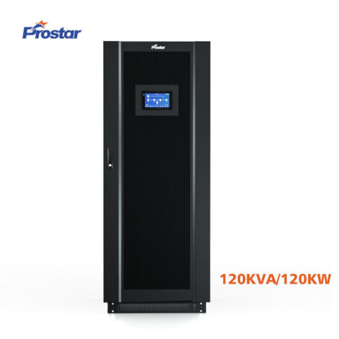
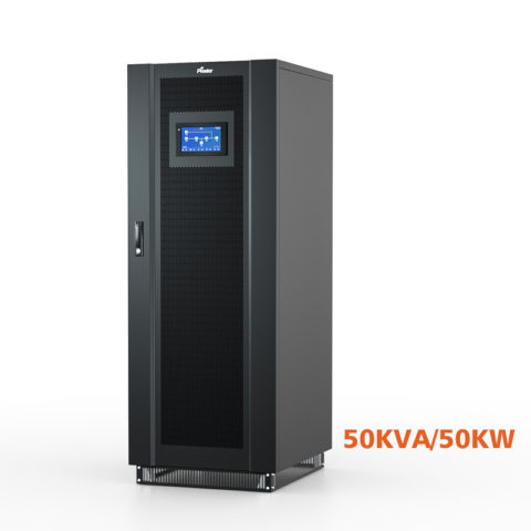
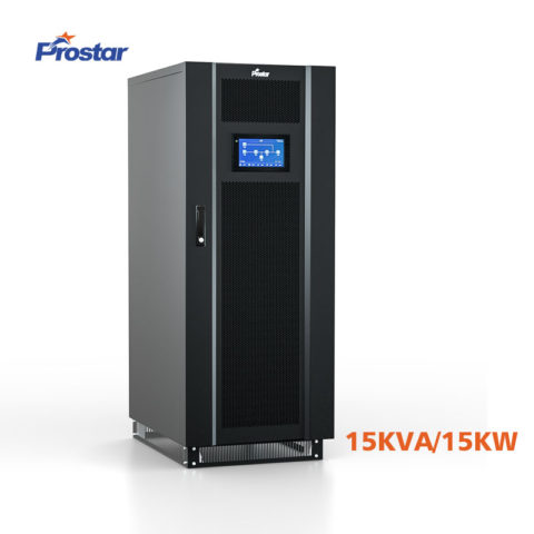
Worked Calculation Example
| Load Component | Active Power (kW) | Operational Load Profile / PF | Multiplier Applied | Required Capacity (kVA) |
| 5× PLCs, HMIs & IPCs | 10 kW | SMPS (PF = 0.70) -> 14.3 kVA | kcrest = 1.20 | 17.2 kVA |
| 4× VFDs (6-pulse, with line reactors) | 100 kW | VFD (PF = 0.88, η = 0.96) -> 118.3 kVA | kTHD = 1.15 | 136.0 kVA |
| Control Panels (24VDC, Solenoids) | 15 kW | Inductive (PF = 0.70) -> 21.4 kVA | kinrush = 1.15 | 24.6 kVA |
| Subtotal Baseline Apparent Power | 125 kW | — | — | 177.8 kVA |
| Expansion Buffer (kexpansion) | — | 25% Headroom Multiplier (1.25x) | — | 222.3 kVA |
| Final Selected UPS Rating | — | Standard Industrial Frame Size | — | 250 kVA / 225 kW |
Industrial UPS Configuration for 25% Load Growth Over Five Years
To accommodate a 25% load expansion over a 5-year operational lifecycle while powering a mix of manufacturing equipment, PLCs, and VFDs, the optimal architecture is a 300 kVA Modular / N+1 Decentralized Parallel Industrial UPS system equipped with Lithium Iron Phosphate (LiFePO4) batteries.
Rather than buying an oversized fixed-capacity unit upfront or risking an expensive forklift upgrade in Year 3, a modular architecture allows you to deploy capacity incrementally while maintaining high operational efficiency and full fault tolerance.
Recommended Engineering Configurations
Depending on your plant layout, floor space constraints, and redundancy requirements, choose between two primary configurations:
Option A: Modular Scalable Architecture (Recommended for Flexibility)
- Initial Deployment (Year 1): 300 kVA Frame populated with 4× 50 kVA / 50 kW Power Modules configured for 150 kW / 187.5 kVA (PF = 0.80) load with N+1 module redundancy (200 kVA active capacity).
- Expansion (Year 3–5): Insert 1× or 2× additional 50 kVA Hot-Swappable Power Modules into the existing frame without interrupting power to downstream PLCs or critical production lines.
- Lowest Total Cost of Ownership (TCO). You only purchase the power module hardware when the new manufacturing line is installed.
Option B: Standalone Monolithic Configuration (Recommended for High Dust/Harsh Zones)
- Deployment (Year 1): 1× 300 kVA / 270 kW Monolithic Online Double-Conversion UPS with an integrated output isolation transformer and an IP42 / NEMA 12 enclosure.
- Operating Profile:
- Year 1 Baseline Load (150 kW / 187.5 kVA): Operating at 62.5% loading capacity—the sweet spot for double-conversion energy efficiency (typically 96.5% efficiency).
- Year 5 Expanded Load (187.5 kW / 234.4 kVA): Operating at 78.1% loading capacity, comfortably accommodating the 25% growth plus motor inrush headroom.
Technical Specification Matrix: 5-Year Expansion Ready System
| Subsystem | Baseline Requirement (Year 1) | Expanded System (Year 5) | Engineering Rationale |
| Active Load Baseline | 150 kW (187.5 kVA @ 0.8 PF) | 187.5 kW (234.4 kVA @ 0.8 PF) | Incorporates 25% plant automation expansion. |
| UPS System Capacity | 300 kVA / 300 kW Frame | 300 kVA / 300 kW Frame | Ensures inverter never exceeds 80% continuous load. |
| Inverter Topology | 3-Level IGBT Double-Conversion | 3-Level IGBT Double-Conversion | Handles high crest factors (3:1) and VFD harmonic THDi. |
| Isolation Transformer | Integrated Output Delta-Wye | Integrated Output Delta-Wye | Eliminates zero-sequence ground noise for PLC/HMI buses. |
| Battery Energy Storage | LiFePO4 (15-min autonomy) | LiFePO4 (15-min autonomy) | Modular rack design; add battery strings in parallel as load grows. |
FAQ
Galvanic isolation transformers separate the primary supply from the secondary critical load, blocking common-mode noise, high-voltage transients, and ground loops from reaching sensitive control hardware (PLCs, SCADA nodes, CNC machinery). They also prevent DC injection into the load circuit if inverter IGBTs fail, attenuate non-linear load harmonics, and enable a local isolated Neutral-Ground bond for standard TN-S grounding.
Nominal power ratings alone cannot establish suitability. The design must show the UPS can supply combined running load and starting transient without exceeding inverter current limits, overload duration, kVA capability, or permissible voltage deviation.
Selection should be based on motor-starting calculations and manufacturer-verified transient performance. If starting current exceeds inverter capability, consider a higher-rated UPS, controlled starting, load sequencing, or a separate motor supply.
Industrial automated loads (such as servo drives, robotic arms, and overhead cranes) frequently dump regenerative energy back into the power system during braking cycles. Standard online double-conversion UPS units cannot absorb back-fed energy, leading to DC bus overvoltage trips. To stabilize the system, engineers must incorporate dynamic braking resistors (DBRs), regenerative active front-end (AFE) drives, or select an industrial UPS designed with internal reverse-power absorption circuits.
The Articles You may Like
- How to Choose 3 Phase Online UPS for Laser Cutting Machine
- Stand-alone power system – Wikipedia
- What is the CT Sensor in Solar Inverter On Off Grid
- Rack Mount UPS – How to Choose for Servers and Home Network?
- Customizable UPS Solutions for Reliable Power Protection
- DSP Based Industrial UPS for Mission-Critical Loads