
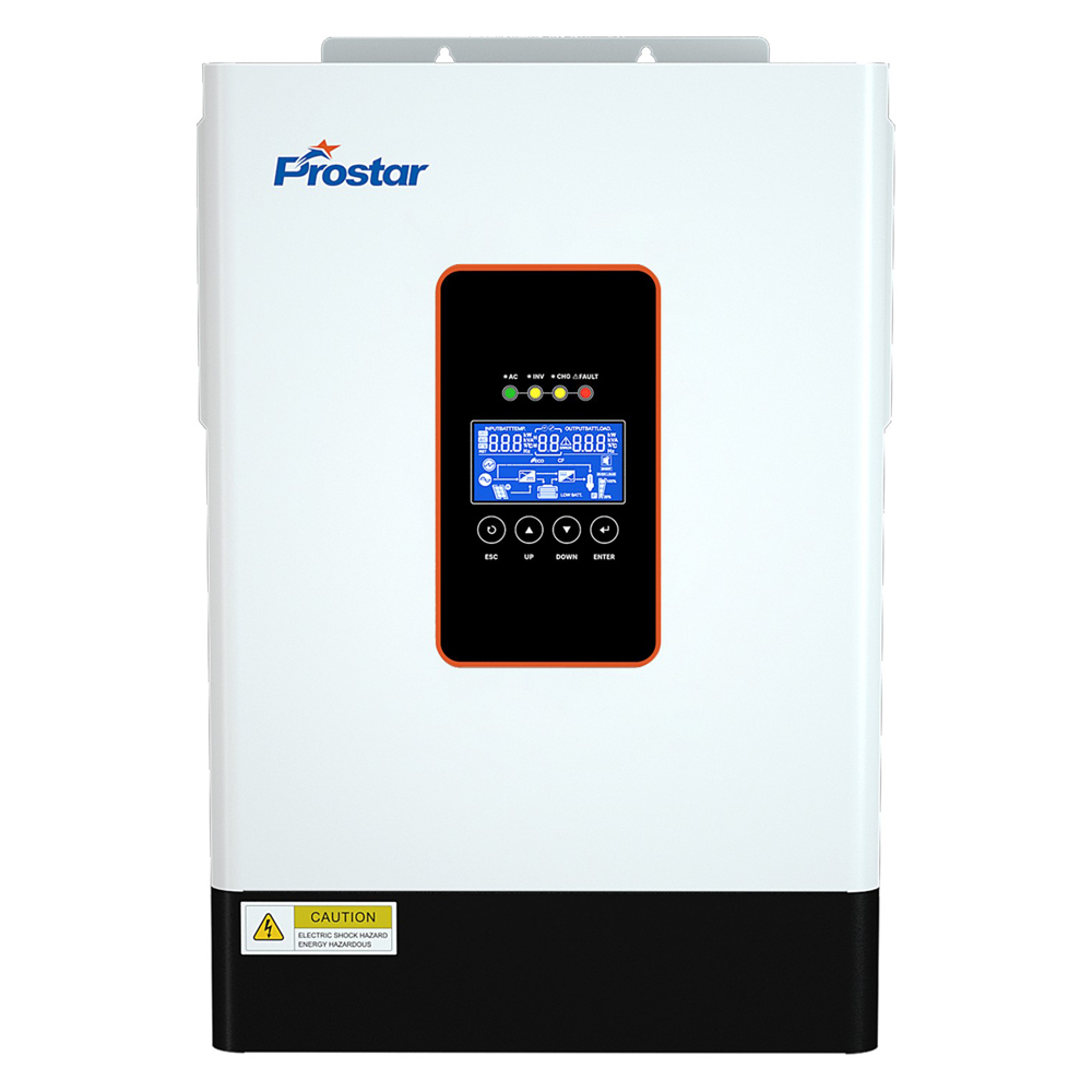
Prostar PIE3.6K-24L hybrid 24v inverter 3600w for residential solar systems, up to 5,000W PV input, and 100A maximum charging current. With grid-tie functionality, 7,200VA surge power, and compatibility with lead-acid and lithium-ion batteries, it supports flexible home solar and backup power applications.
The demand for residential solar power systems continues to grow as homeowners seek to reduce electricity costs and improve energy independence. A reliable inverter is essential for converting solar energy into usable AC electricity and managing different power sources.
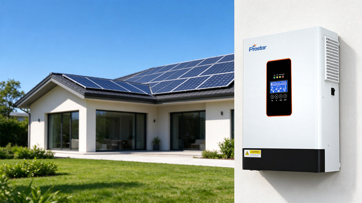
The Prostar PIE3.6K-24L 24V inverter 3600W combines solar charging, battery management, AC power conversion, and grid integration in one compact wall-mounted unit.
Its 24VDC battery architecture makes it suitable for residential energy storage configurations requiring a low-voltage battery system.
Key Features of 24V Inverter 3600W
3.6kW Rated Output for Residential Electrical Loads
The PIE3.6K-24L 24v inverter delivers a rated output of 3.6kW, with a rated apparent power of 3.6kVA. Its power factor is 1.
This means the inverter can supply up to 3,600W of active power under its rated operating conditions.
Typical residential applications include:
-
LED lighting and household lighting circuits.
-
Refrigerators and freezers.
-
Television sets and entertainment systems.
-
Desktop computers and networking equipment.
-
Washing machines within the inverter’s load limits.
-
Small household pumps and other electrical appliances.
The inverter also provides a surge capacity of 6,700VA to accommodate temporary startup demands.

24V DC Battery System with High Charging Capacity
The 24V battery architecture allows the system to operate with a 24V battery bank.
The specified battery parameters are:
| Battery Parameter | Specification |
|---|---|
| Nominal Battery Voltage | 24VDC |
| Floating Charge Voltage | 27VDC |
| Overcharge Protection Voltage | 30.5VDC |
| Maximum PV Charging Current | 100A |
| Maximum AC Charging Current | 100A |
| Maximum Combined Charging Current | 100A |
The inverter supports multi-stage battery charging, including:
-
Constant Current (CC).
-
Constant Voltage (CV).
-
Float charging.
These charging stages regulate battery charging according to the selected charging configuration.
For residential installations, the battery capacity should be selected according to the expected load and required backup duration.
Why does the 24V configuration matter?
It allows the use of a relatively low-voltage battery bank while supporting a 3.6kW output. However, the DC current is substantial.
At full rated output, assuming 92.7% conversion efficiency:
Therefore, battery cables, DC breakers, terminals, and busbars must be appropriately rated for the operating current and installation conditions.
5,000W Maximum PV Input with Wide MPPT Voltage Range
Solar panel compatibility is an important consideration when selecting a residential solar inverter.
An appropriately sized PV array helps increase daily solar energy generation and provides more flexibility when designing the system.
The PIE3.6K-24L supports up to 5,000W maximum PV array power.
PV Input Specifications
| Parameter | Specification |
|---|---|
| Maximum PV array power | 5,000W |
| Maximum PV input current | 18A |
| Maximum PV open-circuit voltage | 500VDC |
| MPPT operating voltage | 40–450VDC |
| Number of MPPT trackers | 1 |
| Strings per MPPT | 1 |
| Maximum PV charging current | 100A |
Wide MPPT operating voltage
The 40–450VDC MPPT operating range provides flexibility when configuring solar panel strings.
Installers can select an appropriate panel arrangement according to the module specifications and site conditions.
High PV array capacity
The 5,000W maximum PV input allows the system to accommodate a solar array larger than the inverter’s 3,600W AC rated output.
This provides additional flexibility in solar system sizing.
High PV charging capability
The maximum PV charging current reaches 100A.
This supports charging a 24V battery bank from the connected solar array, subject to available PV power and battery charging limits.
Grid-Tie Function for Flexible Energy Management
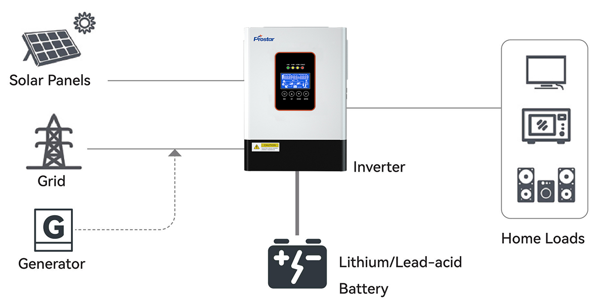
The PIE3.6K-24L supports a grid-tie function, allowing it to be integrated into a residential solar energy system with utility-grid connectivity.

This expands its application beyond a conventional standalone battery inverter.
Depending on the configured operating mode and applicable grid requirements, solar energy can contribute to household power consumption, while the battery and utility supply provide additional energy support.
The grid-tie function is particularly relevant for homeowners who want to combine photovoltaic generation, battery storage, and utility electricity.
Grid connection must follow the applicable local utility interconnection requirements. Confirm the supported grid configuration and export permissions before installation.
Grid and Generator Input Specifications
| Parameter | Specification |
|---|---|
| Nominal input voltage | 208/220/230/240VAC |
| UPS mode voltage range | 170–264VAC |
| APL/GEN mode voltage range | 90–280VAC |
| Nominal frequency | 50Hz/60Hz |
| Frequency operating range | 40–70Hz |
| Frequency detection | Automatic |
| Input power factor | ≥0.99 |
Wide AC input voltage range
The 170–264VAC input range in UPS mode accommodates a range of utility voltage variations.
APL/GEN mode extends the selectable input range to 90–280VAC.
This is useful in locations where utility voltage is unstable or generator output varies.
Generator compatibility
The wide input voltage range and 40–70Hz operating frequency range provide flexibility for generator-supported residential installations.
Generator compatibility should be verified against the generator’s actual voltage and frequency characteristics.
Grid integration
The supported grid-tie function allows the inverter to be incorporated into compatible grid-connected solar configurations.
The exact operating modes, including grid export and self-consumption behavior, should be confirmed against the manufacturer’s operating documentation before system design.
92.7% Maximum Battery-Mode Efficiency
Conversion efficiency directly affects how much usable AC energy can be obtained from the battery.
The PIE3.6K-24L has a specified maximum efficiency of 92.7% in battery mode at 24VDC.
For example, at 3,600W AC output, the estimated DC input power is:
This represents approximately 283.5W of conversion losses under the assumed operating condition.
Actual efficiency varies with load level, battery voltage, temperature, and operating conditions.
For residential solar system designers, this figure helps estimate battery-side power requirements and overall energy consumption.
Fast Transfer Time for Household Backup Power
Power interruptions can affect computers, communication equipment, and household appliances.
A residential backup inverter should switch between power sources within a specified transfer time.
The PIE3.6K-24L provides two transfer-time ratings.
| Connected Load | Transfer Time |
|---|---|
| Personal computers | 10ms |
| Home appliances | 20ms |
10ms transfer time for personal computers
The 10ms transfer specification helps minimize interruptions when the inverter changes between available power sources.
It is suitable for many residential computer and networking applications.
20ms transfer time for home appliances
The 20ms transfer specification supports backup power applications for common household equipment.
However, equipment with strict no-break requirements should be tested for compatibility.
For critical IT equipment, a dedicated online double-conversion UPS may be more appropriate.
Intelligent Monitoring and Communication Interfaces
Monitoring helps homeowners and installers understand system operating conditions.

It also supports maintenance and troubleshooting.
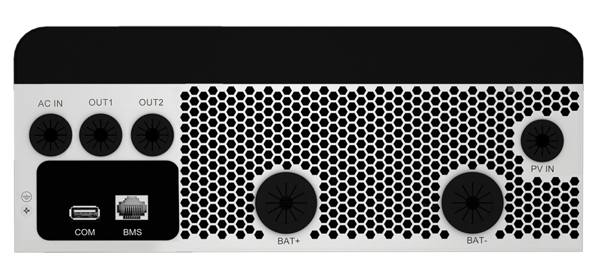
The PIE3.6K-24L includes a local display and communication interfaces.
Monitoring Specifications
| Interface | Function |
|---|---|
| 2.7-inch LCD | Operating parameter display |
| LED indicators | Operating status indication |
| USB (COM) | Communication interface |
| RS485 (BMS) | Battery management communication |
| CT sensor/meter | Optional measurement interface |
| Wi-Fi | Optional remote monitoring |
| GPRS | Optional remote monitoring |
| Ethernet | Optional remote monitoring |
2.7-inch LCD display
Users can check operating information directly from the inverter.
The LED indicators provide additional system status information.
RS485 BMS communication
The RS485 interface supports communication with compatible battery management systems.
This helps coordinate inverter charging parameters with lithium battery operating requirements.
Optional remote monitoring
Wi-Fi, GPRS, and Ethernet modules are available as optional configurations.
Installers and homeowners can select a suitable monitoring solution according to network availability and project requirements.
Technical Specifications
The following table summarizes the available manufacturer specifications.
Electrical and Battery Specifications
| Item | PIE3.6K-24L |
|---|---|
| Rated Capacity | 3.6kVA / 3.6kW |
| Power Factor | 1 |
| Input Voltage | 208/220/230/240VAC |
| Acceptable Input Voltage Range | 90–280VAC (Normal Mode); 170–280VAC (UPS Mode) |
| Input Frequency | 40–70Hz |
| Output Voltage | 208/220/230/240VAC ±5% |
| Surge Capacity | 6,700VA |
| Battery Voltage | 24VDC |
| Floating Charge Voltage | 27VDC |
| Overcharge Protection | 30.5VDC |
| Maximum Battery-Mode Efficiency | 92.7% |
| Parallel Operation | Not supported |
| Grid-Tie Function | Supported |
Solar Charging and Physical Specifications
| Item | PIE3.6K-24L |
|---|---|
| Solar Charger | MPPT |
| Maximum PV Input Power | 5,000W |
| Maximum PV Input Current | 18A |
| MPPT Voltage Range | 40–450VDC |
| Maximum PV Open-Circuit Voltage | 500VDC |
| Maximum PV Charging Current | 100A |
| Maximum AC Charging Current | 100A |
| Maximum Combined Charging Current | 100A |
| Dimensions (D × W × H) | 435 × 285 × 110mm |
| Net Weight | 6.6kg |
PIE3.6K-24L vs. Other Model Capacities
Choosing an inverter requires matching rated power, battery voltage, and PV array capacity to the actual household energy demand.
The following comparison shows the different capacities available within the Prostar PIE product family.
| Parameter | PIE1.2K-12L | PIE3.6K-24L | PIE6.5K-48L |
|---|---|---|---|
| Rated Power | 1.2kW | 3.6kW | 6.5kW |
| Battery Voltage | 12V | 24V | 48V |
| Maximum PV Input Power | 800W | 5,000W | 9,000W |
| MPPT Range | 17–115V | 40–450V | 60–450V |
| Maximum PV Charging Current | 50A | 100A | 120A |
| Maximum PV Open-Circuit Voltage | 115V | 500V | 500V |
| Maximum Efficiency | 90% | 92.7% | 94% |
The PIE3.6K-24L occupies the middle capacity range.
It provides more output power and PV input capacity than the 1.2kW model, while retaining a 24V battery architecture.
The 6.5kW model uses a 48V battery system and is more appropriate when a larger output capacity is required.
Typical Applications
The PIE3.6K-24L is designed for single-phase residential solar applications.
Its electrical specifications support several installation scenarios.
Residential rooftop solar systems
Converts DC electricity generated by rooftop PV modules into usable AC power for household loads.
Home battery storage systems
Supports compatible 24V lead-acid and lithium-ion battery configurations for residential energy storage.
Off-grid residential power systems
Provides AC power from solar and battery sources for homes in areas with limited grid access.
Solar and generator hybrid systems
Supports generator-compatible AC input configurations for residential backup power applications.
How to Design a 24V Solar System with a 3600W Inverter
Correct system sizing is necessary to achieve stable operation and protect connected equipment.
A 24V inverter 3600W system requires particular attention to battery discharge current and DC cable sizing.
Calculate the Required Battery Capacity
Battery capacity determines how long the inverter can supply power when solar generation or utility electricity is unavailable.
The following formula provides an initial battery-sizing estimate:
Where:
-
E = Required AC energy (Wh).
-
P = Average AC load (W).
-
t = Backup duration (hours).
For example, consider a household requiring 1,500W of continuous power for four hours.
| Parameter | Value |
|---|---|
| Average AC Load | 1,500W |
| Required Backup Time | 4 hours |
| AC Energy Requirement | 6,000Wh |
| Inverter Efficiency Assumption | 92.7% |
| Estimated DC Energy Requirement | 6,472Wh |
The theoretical battery capacity at 24V is:
This is a theoretical minimum before accounting for battery depth of discharge, temperature, aging, voltage drop, and reserve capacity.
The actual battery bank should be sized with an appropriate engineering margin.
Configure the Solar Panel Array
The inverter supports a maximum PV input power of 5,000W.
Its MPPT operating voltage range is 40–450VDC, with a maximum PV open-circuit voltage of 500VDC.
Solar panel string design must consider:
-
Total PV array power.
-
Maximum PV input current of 18A.
-
String operating voltage under different temperatures.
-
Maximum open-circuit voltage under the lowest expected temperature.
-
Compatibility with the inverter’s PV input configuration.
A PV string should never exceed the inverter’s maximum voltage or current ratings.
For example, using a 630W bifacial dual-glass solar module as a reference:
- Max. Power – Pmax: 630W
- Max. Power Voltage – Vmp: 41.02V
- Max. Power Current – Imp: 15.36A
- Open-circuit Voltage – Voc: 49.48V
- Short-circuit Current – Isc: 16.20A
- Efficiency: 23.3%
Step 1: Quantity Determination
5000W / 630W = 7.93 — select 8 modules in series
Step 2: String Open-Circuit Voltage Check
Voc = 49.48V * 8 = 395.84V (Safe, <500VDC)
Step 3: String Current Check
Imp = 15.36A (Safe, <18A)
Connect 8 x 630W solar panels in a single series string.
Select Appropriate DC Protection and Cabling
At 3.6kW output, the battery-side current can exceed 160A under nominal 24V operation.
This makes DC-side engineering particularly important.
Recommended design considerations include:
-
Properly rated DC circuit breakers or fuses.
-
Battery cables sized for continuous current and installation conditions.
-
Short DC cable runs to reduce voltage drop.
-
Correct cable lug crimping and terminal connections.
-
Appropriate battery isolation and overcurrent protection.
-
Adequate ventilation around the inverter and battery bank.
For a 24V inverter 3600W installation, undersized battery cables can cause excessive voltage drop, overheating, and unexpected inverter shutdown.
International Standards and Installation Compliance
Residential solar installations must comply with the electrical safety and grid-interconnection requirements of the installation country.
Relevant international standards and technical references include:
| Standard | Technical Scope |
|---|---|
| IEC 62109-1 | General safety requirements for power converters used in photovoltaic systems |
| IEC 62109-2 | Particular safety requirements for inverters |
| IEC 60364-7-712 | Electrical installations incorporating photovoltaic power supply systems |
| IEC 62446-1 | Documentation, commissioning tests, and inspection of PV systems |
| IEC 61643-31 | Surge protective devices for photovoltaic installations |
These standards provide useful references for system design, equipment selection, installation, and commissioning.
Frequently Asked Questions (FAQ)
The Articles You may Like
-
- How to Choose 3 Phase Online UPS for Laser Cutting Machine
- Split-phase electric power – Wikipedia
- What is the CT Sensor in Solar Inverter On Off Grid
- Select the Right Uninterruptible Power System for Harsh Oil and Gas Environments
- How 3 Phase Lithium UPS System Enhances Backup Power Performance
- Top 5 Benefits of Installing Solar Battery Backup System