
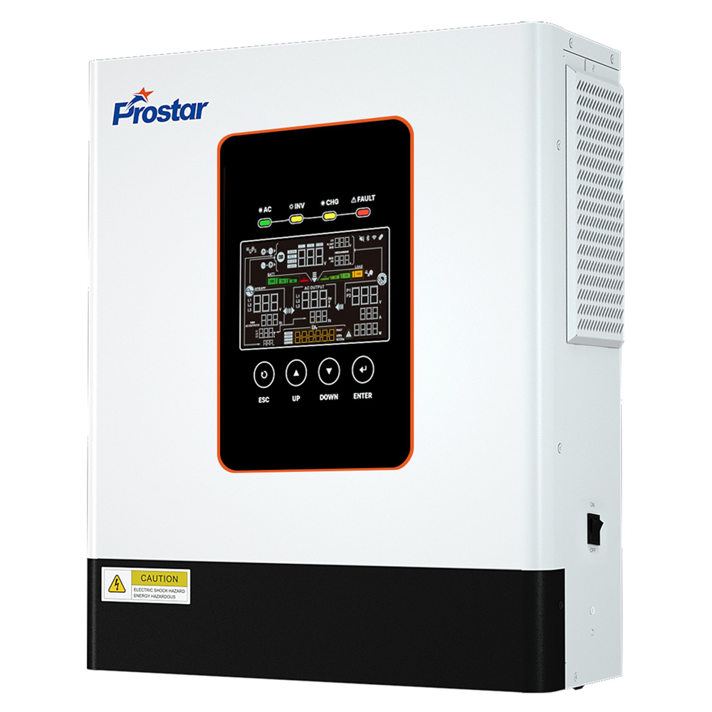
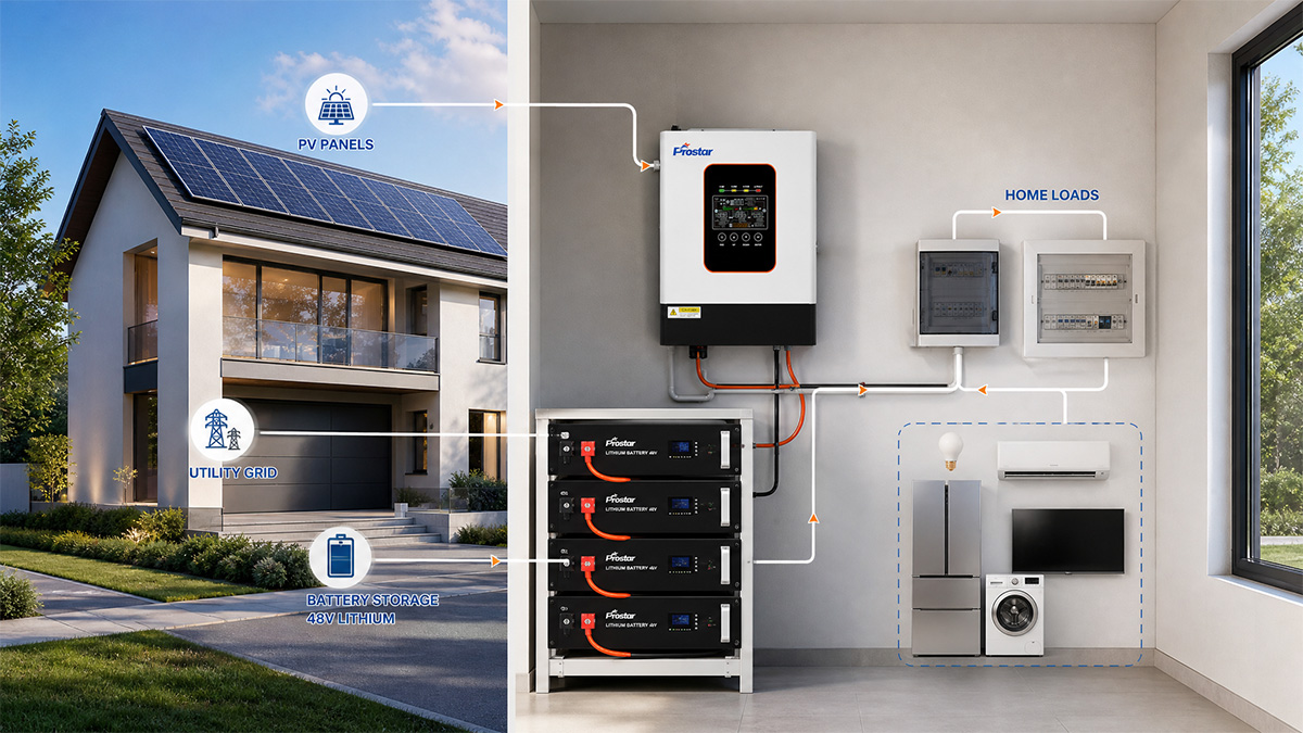
Prostar PIE6.5K-48L 6500w inverter hybrid solar 48v for home solar systems supports up to 9,000W PV input, 48V battery storage, battery-free operation, and 120A maximum charging current. With 12kVA surge power, pure sine wave output, and grid integration, it provides flexible solar power management for homes and small commercial applications.
The PIE6.5K-48L inverter hybrid solar is a 48V single-phase solar inverter designed to convert photovoltaic energy into usable AC electricity while managing grid power and battery storage.
It combines solar power conversion, battery charging, and AC power management in one compact wall-mounted unit.
Unlike conventional battery-dependent solar inverters, the PIE6.5K-48L also supports battery-free operation.
Users can operate connected loads directly from PV or grid power without installing batteries at the initial stage.
This makes the inverter suitable for homeowners who want to reduce electricity costs through solar generation while retaining the option to add battery storage later.
Key Features
6,500W Rated Output with 12kVA Surge Capacity
High Continuous Power and Additional Surge Capacity
The PIE6.5K-48L delivers 6,500VA / 6,500W rated output power.
It also provides up to 12kVA surge power for temporary high-power demands.
The single-phase output supports four selectable voltage levels:
-
208VAC
-
220VAC
-
230VAC
-
240VAC
The output voltage regulation is ±5%.
Supports Multiple Household Electrical Loads
A 6.5kW inverter hybrid solar can supply several electrical appliances simultaneously, depending on their combined operating power.
Typical applications include:
-
Refrigerators and freezers.
-
LED lighting systems.
-
Computers and networking equipment.
-
Washing machines.
-
Air conditioning systems.
-
Water pumps.
-
Kitchen appliances.
The additional surge capacity helps accommodate temporary startup demands from motor-driven equipment.
More Flexible Residential Power Distribution
Homeowners can operate multiple electrical loads through one centralized power conversion system.
The 12kVA surge rating provides additional short-term capacity beyond the nominal 6.5kW output.
However, actual motor-starting compatibility depends on surge duration, motor starting current, power factor, and the inverter’s overload protection characteristics.
9kW Maximum PV Input for Higher Solar Energy Harvesting
Supports Up to 9,000W Solar Panel Capacity
The PIE6.5K-48L supports a maximum PV array power of 9,000W.
Its PV input specifications include:
| PV Input Parameter | Specification |
|---|---|
| Maximum PV Array Power | 9,000W |
| Maximum PV Input Current | 27A |
| Maximum PV Open-Circuit Voltage | 500VDC |
| MPPT Operating Voltage | 60–450VDC |
| MPPT Trackers | 1 |
| Strings per MPPT | 1 |
More Solar Generation Capacity
The 9kW PV input rating allows the connected solar array to have a higher nominal capacity than the inverter’s 6.5kW AC output rating.
This provides additional flexibility when designing residential solar installations.
A larger PV array can help increase energy production during periods of lower solar irradiance, such as early mornings, late afternoons, or cloudy conditions.
The actual energy yield depends on panel orientation, shading, temperature, location, and system configuration.

Better Utilization of Available Solar Resources
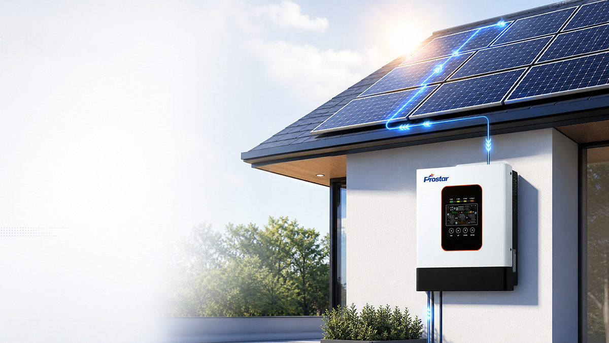
Homeowners can install a larger PV array to increase the potential availability of solar electricity throughout the day.
This can help reduce grid electricity consumption and improve the utilization of the inverter’s rated output capacity.
Battery-Free Operation: Start with Solar Without Battery Investment
Supports Battery-Free Solar Operation
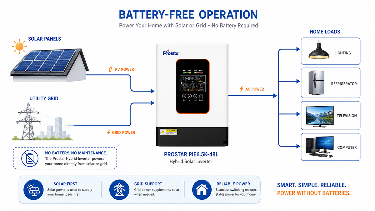
One distinguishing feature of the PIE6.5K-48L is its ability to operate without a connected battery.
The inverter hybrid solar can supply connected loads directly using available PV or grid power.
Battery installation is not mandatory for initial system operation.
Flexible Solar System Configuration
Traditional battery-based solar installations require an additional investment in energy storage.
The PIE6.5K-48L allows users to begin with a PV and grid-connected configuration.
A battery bank can be added later when backup power or energy storage becomes necessary.
Lower Initial Installation Costs
This operating mode is suitable for homeowners who want to prioritize daytime solar self-consumption.
It offers several practical advantages:
-
No mandatory battery purchase.
-
Lower initial system investment.
-
Simplified initial system configuration.
-
Flexible future battery expansion.
-
Reduced dependence on grid electricity when solar generation is available.
Battery-Free vs. Battery-Based Solar Systems
| Comparison | Battery-Free Configuration | Battery-Based Configuration |
|---|---|---|
| PV Power Utilization | Supported | Supported |
| Grid Power | Supported | Supported |
| Battery Required | No | Yes |
| Energy Storage | Not available | Available |
| Backup During Grid Failure | Not provided by battery storage | Depends on battery availability and inverter operating mode |
| Initial Investment | Lower | Higher |
| Nighttime Solar Supply | Not available | Possible using stored energy |
Important: Battery-free operation does not mean uninterrupted power during a grid outage. Without a battery, the inverter cannot provide stored-energy backup when solar generation is insufficient.
48V Battery Compatibility with 120A Maximum Charging Current
Supports Multiple Battery Technologies
The PIE6.5K-48L 6500w inverter hybrid solar uses a 48VDC nominal battery system.
It supports three battery configuration options:
-
Lead-acid batteries.
-
Lithium-ion batteries.
-
User-defined battery parameters.
Its charging specifications are:
| Charging Parameter | Specification |
|---|---|
| Nominal Battery Voltage | 48VDC |
| Maximum PV Charging Current | 120A |
| Maximum AC Charging Current | 120A |
| Maximum Hybrid Charging Current | 120A |
| Floating Charge Voltage | 54VDC |
| Overcharge Protection | 61VDC |
| Charging Algorithms | 2-stage / 3-stage / PV Charging |
Flexible Battery Selection and Charging Management
Different residential solar projects have different energy storage requirements.
Some users prefer lead-acid batteries because of their initial purchase cost.
Others select lithium-ion batteries for their energy density and battery management capabilities.
The inverter supports configurable charging parameters to accommodate different battery requirements.
Available charging algorithms include:
-
Two-stage charging: CC / Float.
-
Three-stage charging: CC / CV / Float.
-
PV charging mode.
Adaptable Energy Storage for Different Applications
The 120A maximum charging capability supports high-current battery charging.
This helps improve battery energy replenishment when sufficient PV or AC charging power is available.
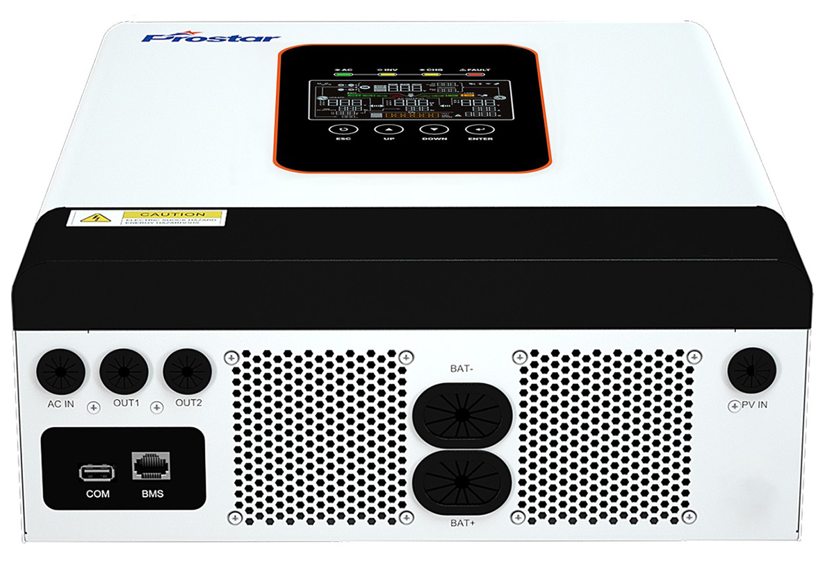
For lithium battery installations, the RS485 BMS communication interface supports battery management communication.
Installers should confirm battery voltage limits, charging current limits, BMS compatibility, and communication protocols before commissioning.

Grid-Tie Function for Solar and Utility Integration
Multiple AC Input Voltage Options
The PIE6.5K-48L hybrid solar inverter 6500w supports grid-connected operation and accepts the following nominal AC input voltages:
-
208VAC.
-
220VAC.
-
230VAC.
-
240VAC.
Its selectable input voltage ranges are:
| Operating Mode | AC Input Voltage Range |
|---|---|
| UPS Mode | 170–264VAC |
| APL / GEN Mode | 90–280VAC |
The inverter hybrid solar also supports automatic frequency sensing for 50Hz and 60Hz systems.
Its specified frequency operating range is 40–70Hz.
Adaptable to Different Grid Conditions
The wide input voltage range allows the inverter to accommodate different utility supply conditions.
The APL / GEN mode also provides additional flexibility when working with generator power sources.
This is useful in locations where grid voltage fluctuates or generators are used as supplementary power sources.
Flexible Residential Energy Management
The inverter combines PV generation and utility power within one system.
Users can utilize available solar electricity and draw grid power when required.
This helps reduce dependence on conventional electricity supplies while maintaining access to utility power.
Technical clarification: The product specification confirms grid-tie functionality. However, grid export, anti-islanding protection, and utility interconnection certification must be verified for the intended market before the inverter is used for feeding surplus electricity into the public grid.
Fast Transfer Time for Connected Loads
10ms / 20ms Transfer Time
The inverter provides different specified transfer times depending on the connected load category.
| Load Category | Transfer Time |
|---|---|
| Personal Computers | 10ms |
| Home Appliances | 20ms |
Rapid Switching Between Available Power Sources
When operating conditions require a transfer between power sources, the inverter provides a short transition time.
Helps Minimize Power Interruption
This is useful for residential applications where brief power interruptions can affect electronic devices.
Typical applications include:
-
Home computers.
-
Internet routers.
-
CCTV systems.
-
Smart home controllers.
-
Household electronic equipment.
Transfer time is not equivalent to zero-interruption online UPS performance. Equipment compatibility should be verified, particularly for sensitive loads.
Operating Environment and Application Conditions
The PIE6.5K-48L all in one hybrid solar inverter is designed to operate across a range of environmental conditions.
| Environmental Parameter | Specification |
|---|---|
| Operating Temperature | -10°C to 60°C |
| Storage Temperature | -15°C to 60°C |
| Relative Humidity | 5%–95%, non-condensing |
| Protection Rating | IP21 |
| Cooling | Intelligent Fan Cooling |
| Noise Level | Below 45dB at 1m |
Installers should consider ambient temperature, ventilation, mounting clearance, humidity, and dust exposure.
For high-temperature installations, appropriate ventilation is necessary to maintain operating conditions.
Product Specifications
| Parameter | Specification |
|---|---|
| Model | PIE6.5K-48L |
| Rated Power | 6,500VA / 6,500W |
| Phase | Single-phase, L+N+PE |
| Battery Voltage | 48VDC |
| Maximum PV Array Power | 9,000W |
| Maximum PV Input Current | 27A |
| Maximum PV Voltage | 500VDC |
| MPPT Voltage Range | 60–450VDC |
| Maximum Charging Current | 120A |
| Surge Power | 12kVA |
| Output Voltage | 208 / 220 / 230 / 240VAC |
| Maximum DC-to-AC Efficiency | 94% |
| Output Waveform | Pure Sine Wave |
| Grid-Tie Function | Supported |
| Battery-Free Operation | Supported |
| Installation | Wall-mounted |
| Dimensions | 410 × 336 × 125mm |
| Net Weight | 8.5kg |
Typical Applications
The PIE6.5K-48L inverter hybrid solar system is designed for applications requiring residential solar generation, grid integration, and optional battery storage.
Residential Rooftop Solar Systems
Supports household electricity generation using solar panels, with a 6.5kW rated output and 9kW maximum PV input.
Home Solar Energy Storage
Compatible with 48V lead-acid and lithium-ion battery systems for residential energy storage applications.
Small Commercial Buildings
Suitable for shops, offices, and small businesses requiring solar-assisted electricity.
Solar and Generator Hybrid Systems
Supports AC input from compatible generator sources, providing additional flexibility where utility power is unstable.
Sizing Guide: Matching Loads and Storage
Selecting the right single phase hybrid solar inverter requires balancing daytime consumption, peak surge loads, and overnight autonomy.
| Home Profile | Recommended PV Array | Recommended 48V Battery | Typical Supported Appliances |
| Starter Grid-Tie (No Battery) | 6.0kW – 9.0kW | 0 kWh (Expandable later) | Daytime HVAC, pool pump, washer/dryer |
| Standard Backup Home | 6.5kW – 8.0kW | 10 kWh (51.2V 200Ah LiFePO4) | Lights, Wi-Fi, fridge, TV, 1x split AC |
| Full Energy Independence | 8.5kW – 9.0kW | 16 kWh (51.2V 314Ah LiFePO4) | Whole-home loads, well pump, home office |
How to Install 6500W Inverter Hybrid Solar
To install a 6.5kW 48V hybrid solar inverter, follow the step-by-step procedures covering mounting, electrical wiring, safety protections, and initial startup:
Pre-Installation & Mounting Requirements
- All mechanical and electrical work must be performed by qualified electrical personnel following local safety standards.
- Mount the inverter vertically on a solid concrete or non-combustible wall. Do not mount it on flammable building materials.
- Maintain at least 30 cm clearance on all sides (top, bottom, left, and right) to ensure sufficient airflow for heat dissipation.
- Mounting Steps:
- Drill wall holes using an 8 mm drill bit spaced 160 mm apart horizontally.
- Insert M6 expansion screws/tubes.
- Lift the inverter vertically, align the top mounting holes with the expansion screws, and fix the unit securely to the wall.
- Remove the bottom cover by unscrewing 4 screws to expose the electrical terminal blocks.
External Protective Grounding (PE)
- Connect a yellow-green protective earth (PE) ground cable to the inverter’s external grounding point using an OT terminal and M4 screw to prevent electric shock hazards.
AC Input & Output Wiring
- Install a separate 40A AC circuit breaker between the utility grid/generator and the inverter’s AC input port.
- Recommended Cable Sizes:
- AC Input Wires: 10 AWG (5.26 mm²)
- AC Output Wires (OUT1 & OUT2): 12 AWG (4.0 mm²)
- Wiring Connection:
- Strip cable insulation (12 mm) and crimp conductors tightly using tubular terminals.
- Connect Line (L), Neutral (N), and Ground (PE) to the corresponding AC IN, AC OUT1, and AC OUT2 terminal blocks according to the marked polarities.
- Safety Warning: Do not connect the input Neutral (N) and output Neutral (N) lines together, as this may damage the inverter.
Photovoltaic (PV) Array Connection
- Install a separate DC circuit breaker between the solar panels and the inverter.
- PV String Specifications:
- Max PV Open Circuit Voltage (Voc): 500 VDC
- MPPT Voltage Window: 60 VDC – 450 VDC
- Start-Up Voltage: 80 VDC
- Max PV Input Power / Current: 9000 W / 27 A
- Recommended Cable: 10 AWG (6 mm²)
- Connect the positive solar string wire to PV+ (red) and the negative wire to PV- (black). Do not ground either the positive or negative PV terminals.
48VDC Battery Connection
- Install a dedicated 150A DC over-current disconnect breaker between the 48V battery bank and the inverter.
- Recommended Cable & Terminals: 2 AWG (25 mm²) battery cable fitted with DT crimp terminals.
- Route battery cables through the bottom shell and tighten them securely to the BAT+ (positive) and BAT- (negative) terminals.
- Lithium BMS Communication Cable (Optional):
- Plug an RJ45 communication cable from the lithium battery BMS into the inverter’s BMS Port.
- Inverter BMS RJ45 Pin Assignment: Pin 1 (RS485B), Pin 2 (RS485A), Pin 4 (CANH), and Pin 5 (CANL).
Final Assembly & Powering On
- Re-check all polarities and connections, then re-attach the bottom cover with its 4 screws.
- Plug the optional Wi-Fi stick into the COM port for cloud mobile APP monitoring.
- Close the battery DC breaker, PV DC breaker, and AC breakers.
- Press the ON/OFF switch located at the bottom of the inverter chassis.
- Hold the ENTER button on the front panel for 2 seconds to enter LCD settings:
- Program 17 (Battery Type): Set to AGM, FLD (Flooded), LIT (Ternary Lithium), or FEL (LiFePO4).
- Program 03 (Output Priority): Set preferred power routing (Grid First, PV First, or PBG Priority).
Frequently Asked Questions (FAQ)
The Articles You may Like
- What is the CT Sensor in Solar Inverter On Off Grid
- Hybrid Solar Inverters Provide Off-grid Power Availability
- Which Transformer is Good for Home Solar Inverter
- Can Off Grid Solar Inverter Charge Controller Run without Battery
- How to Use Off Grid Solar Inverter Without Battery
- Hybrid power – wikipedia