
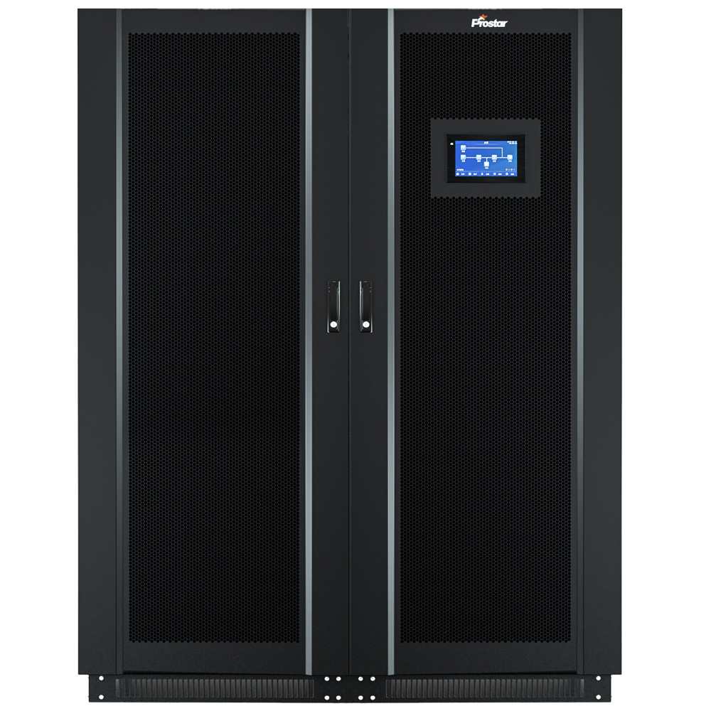
Prostar ET200K is three-phase industrial online UPS 200kVA designed to protect critical equipment against power interruptions and voltage disturbances. It features double-conversion technology, a 1.0 output power factor, less than 3% input current THDi at full load, zero transfer time, and support for up to eight parallel units. VRLA batteries are standard; lithium-ion compatibility is optional.
The system uses online double-conversion technology to regulate output power independently of normal input voltage fluctuations. It delivers a pure sine wave output, supports three-phase, four-wire-plus-protective-earth connections, and provides a nominal output voltage of 380V, 400V, or 415V AC.
For applications requiring higher system capacity or parallel redundancy, the ET200K online UPS 200kVA supports parallel operation of up to 8 units.
Why Choose the ET200K Industrial Online UPS 200kVA?
Selecting an industrial UPS requires more than matching the nominal kVA rating. Engineers must evaluate active power capacity, voltage stability, harmonic distortion, overload performance, battery autonomy, and maintenance requirements.
The ET200K combines a 200kVA rating with 200kW of active power. This makes the online ups 200kva suitable for facilities with high power demand and equipment sensitive to voltage disturbances.
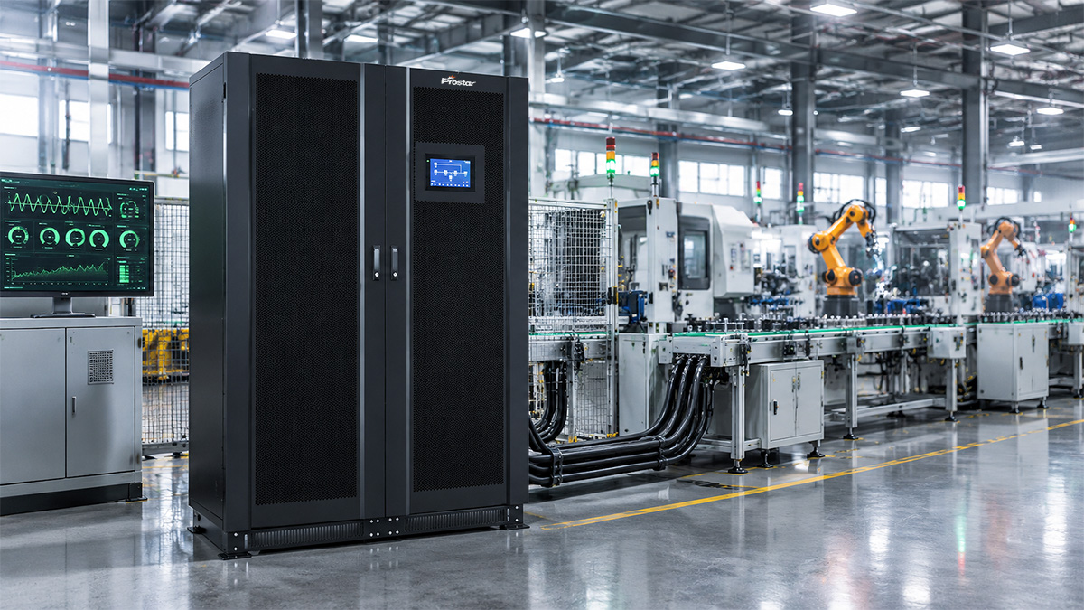

200kVA/200kW Capacity with Unity Power Factor
Many industrial loads require substantial active power to operate motors, automation systems, control equipment, and production machinery. A UPS with a lower output power factor may reach its kW limit before reaching its kVA limit.
The ET200K has a rated output power factor of 1.0.
| Parameter | ET200K specification | Engineering benefit |
|---|---|---|
| Rated apparent power | 200kVA | Defines the UPS capacity in kVA |
| Rated active power | 200kW | Supports up to 200kW of rated active load |
| Output power factor | 1.0 | Makes rated kVA equal to rated kW |
| Output voltage | 380/400/415Vac | Supports common three-phase industrial distribution voltages |
| Output waveform | Pure sine wave | Suitable for sensitive electronic loads |
It means the ET200K can deliver up to 200kW of active power at its rated conditions. Actual system sizing must also account for load current, power factor, harmonic content, transient demand, and the manufacturer’s operating limits.
For example, a facility with a 160kW steady-state load would use 80% of the UPS’s rated active power. This leaves 40kW of nominal active-power headroom, although transient loads and future expansion must be assessed separately.
Online Double-Conversion Technology with Zero Transfer Time
The ET200K uses online double-conversion technology. Incoming AC power is converted to DC and then reconstructed as regulated AC power through the inverter.
This process reduces the effect of input voltage and frequency disturbances on the protected load.
When the UPS transfers from normal operation to battery operation, the specified transfer time is 0ms. This avoids a transfer interruption caused by switching between the normal AC source and battery-powered inverter operation.
Key technical characteristics include:
-
Continuous inverter-based power conditioning.
-
Pure sine wave output.
-
Output voltage regulation of ±1%.
-
Battery-mode output frequency accuracy of ±0.01% at 50Hz or 60Hz.
-
Zero transfer time between mains and battery modes.
For manufacturing plants, this operating principle can help protect PLCs, industrial computers, machine controllers, and other electronic equipment against short-duration supply interruptions.
The actual performance under sudden load changes should be verified against the manufacturer’s dynamic-response test results.
Low Input Harmonic Distortion and Improved Power Quality
High-capacity UPS systems can affect the upstream electrical network through their input current characteristics. Harmonic current distortion can increase losses and interact with other equipment connected to the same supply.
The ET200K specifies an input current total harmonic distortion (THDi) of less than 3% at full load.
Its input power factor is greater than 0.95.
| Electrical parameter | ET200K rating | Practical significance |
|---|---|---|
| Input power factor | Greater than 0.95 | Supports efficient utilization of the upstream supply |
| Input current THDi | Less than 3% at full load | Limits harmonic current distortion under the specified test condition |
| Input voltage range | 304–456Vac | Accommodates input voltage variation |
| Input frequency range | 40–70Hz | Supports a wide range of input frequency conditions |
| Input frequency selection | 50/60Hz, automatic | Adapts to compatible nominal supply frequencies |
These characteristics are relevant to industrial sites with generators, variable-frequency drives, automation equipment, and other nonlinear loads.
However, final generator sizing should consider rectifier behavior, battery charging demand, generator transient response, and the site’s complete load profile. Low THDi alone does not guarantee compatibility with every generator.
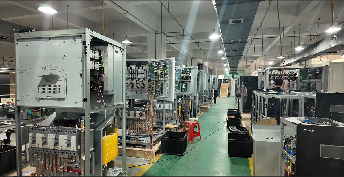

IGBT-Based Rectifier for Improved Input Power Quality
The ET200K online UPS 200kVA uses an IGBT-based rectifier to convert incoming three-phase AC power into DC power for the DC bus. This rectifier topology supports controlled input current, a high input power factor of greater than 0.95, and input current total harmonic distortion (THDi) of less than 3% at full load.
- THDi below 3% at full load helps reduce harmonic current injected into the upstream electrical network.
- Greater than 0.95 supports efficient utilization of the AC supply.
- IGBT switching enables active regulation of input current and DC-bus power, subject to the rectifier’s control design.
- Suitable for applications where input power quality and stable DC-bus operation are important.
Regulated Output for Sensitive Industrial Loads
Industrial electronics may malfunction when voltage deviates beyond the permitted operating range. Repeated disturbances can also cause unnecessary shutdowns and production interruptions.
The ET200K provides an output voltage regulation specification of ±1% and low output voltage harmonic distortion.
| Output characteristic | ET200K specification |
|---|---|
| Rated output voltage | 380/400/415Vac |
| Output voltage regulation | ±1% |
| THDu at 100% linear load | Less than 2% |
| THDu at 100% nonlinear load | Less than 5% |
| Output frequency in battery mode | 50/60Hz ±0.01% |
| Crest factor | 3:1 |
| Output waveform | Pure sine wave |
The low specified THDu helps supply sensitive electronic equipment with a cleaner voltage waveform. The 3:1 crest factor indicates the stated capability to accommodate loads with high peak-to-RMS current ratios, subject to the UPS’s rated current and overload limits.
For equipment with high starting current, such as motors and compressors, engineers must also evaluate starting current, acceleration time, load sequencing, and voltage-dip tolerance.
An online ups 200kva should therefore be selected based on both steady-state demand and transient load requirements.
Built-in Output Isolation Transformer
The ET200K 200kVA industrial online UPS integrates an output isolation transformer to provide galvanic isolation between the UPS inverter output and the connected load. This transformer-based design supports industrial power distribution requirements and offers greater flexibility in output grounding and neutral configuration, subject to the system design.
- Galvanic isolation at the output: Electrically separates the inverter output circuit from the load circuit through the transformer.
- Flexible grounding configuration: Supports grounding and neutral arrangements tailored to the installation requirements.
- Industrial load compatibility: Suitable for industrial automation, manufacturing equipment, process control systems, and other critical loads requiring transformer-based power protection.
- Robust power distribution: Provides an additional transformer interface between the UPS power conversion stage and downstream equipment.
Overload Capacity and Industrial Load Management
Industrial equipment does not always draw a constant amount of power. Motors start and stop. Compressors cycle. CNC machines change operating states. Transformer energization and capacitor charging can also create short-duration current peaks.
The ET200K specifies graduated overload handling, with transfer to bypass at defined load levels and durations.
| Load relative to rated capacity | Specified overload behavior |
|---|---|
| Up to 105% | Continuous operation |
| Above 105% to 110% | Transfer to bypass within 60 minutes |
| Above 110% to 125% | Transfer to bypass within 10 minutes |
| Above 125% to 150% | Transfer to bypass within 1 minute |
| Above 150% to 200% | Transfer to bypass within 200ms |
| Above 200% | Inverter shutdown within 100ms and transfer to bypass output |
These values describe the specified overload response, not a recommendation to operate the UPS continuously above its rated capacity.
A properly sized industrial UPS can accommodate temporary load variations within its documented limits. However, overload operation may transfer the load to bypass, where the load becomes dependent on the bypass supply’s availability and quality.
For demanding applications, confirm the bypass source capacity, upstream protection coordination, and acceptable load interruption risk before finalizing the design.
Energy Efficiency and Operating Cost
Energy efficiency affects the lifetime cost of an industrial UPS. Even a small efficiency difference can result in substantial energy losses when the system operates continuously at high load.
The ET200K specifies:
-
AC-to-AC efficiency above 93% in normal operating mode at full load.
-
ECO mode efficiency above 98%.
Normal Mode vs. ECO Mode
| Comparison | Online double-conversion mode | ECO mode |
|---|---|---|
| Specified efficiency | Greater than 93% at full load | Greater than 98% |
| Main operating principle | Continuous inverter-based power conditioning | Load supplied through the bypass path under acceptable conditions |
| Output conditioning | Continuous double conversion | Depends on bypass supply quality and operating limits |
| Typical priority | Power conditioning and load protection | Energy savings where bypass operation is acceptable |
ECO mode can reduce conversion losses. However, its suitability depends on the site’s power quality requirements and tolerance for changes in operating mode.
For sensitive industrial loads, the efficiency gain should be weighed against the required protection level. Confirm the actual ECO-mode voltage and frequency limits before enabling it.


Illustrative Energy-Loss Calculation
At a hypothetical constant output load of 160kW, using the stated minimum efficiency figures as illustrative calculation points:
-
At 93% efficiency, input power would be approximately 172.0kW, giving about 12.0kW of conversion losses.
-
At 98% efficiency, input power would be approximately 163.3kW, giving about 3.3kW of conversion losses.
The difference is approximately 8.7kW, or 76MWh over 8,760 operating hours.
These are illustrative estimates, not guaranteed operating results. The datasheet values are specified as greater than 93% and greater than 98%; actual efficiency depends on load, configuration, and operating conditions.
Battery Configuration and Backup-Time
The ET200K supports VRLA batteries as standard, with lithium-ion battery compatibility available as an option. Its default DC battery voltage is 384Vdc, with a specified range of 336–384Vdc.
Battery autonomy depends on the connected load, battery capacity, discharge characteristics, ambient temperature, battery age, and inverter efficiency.
| Battery parameter | ET200K specification |
|---|---|
| Standard battery type | VRLA |
| Optional battery type | Lithium-ion |
| Default battery voltage | 360Vdc |
| Specified battery voltage range | 336–384Vdc |
| Charging configuration | Adjustable charging rate, battery capacity, and battery group settings |
| Battery autonomy | Determined by battery configuration and load |
How to Estimate Required Battery Capacity
This calculation evaluates the VRLA lead-acid battery configuration required for the Prostar ET200K 200kVA/200kW industrial online UPS, assuming 100% load and 15 minutes of backup time.
1. Battery Sizing Parameters
| Parameter | Value |
|---|---|
| UPS rated capacity | 200kVA / 200kW |
| Load level | 100% |
| UPS efficiency assumption | 93% |
| Illustrative nominal DC battery voltage | 384VDC |
| Individual battery rated voltage | 12V |
| Batteries connected in series per string | 32 |
| Required backup time | 15 minutes |
| Battery aging factor (EOL) | 1.25 |
| Safety margin | 5% |
| Battery model | 12V, 250Ah VRLA |
| Preliminary capacity target | 750Ah |
| Capacity target including 5% safety margin | 787.5Ah, approximately 788Ah |
The capacity figures above are preliminary design targets. They do not independently establish that the proposed battery bank can supply 200kW for 15 minutes.
2. Required Battery-Side Power
At a 200kW output load and an assumed UPS efficiency of 92%, the estimated DC input power is:
At the nominal battery voltage of 384VDC, the estimated DC current is:
These are preliminary estimates based on nominal battery voltage. Actual battery current will increase as the battery voltage falls during discharge. Final sizing must use the manufacturer’s constant-power discharge data at the specified end-of-discharge voltage.
3. Constant-Current Discharge Data for a 12V, 250Ah Battery
The following manufacturer data show the constant-current discharge capability at 25°C (77°F).
| Time | 15min | 30min | 1hr | 3hr | 5hr | 10hr | 20hr |
| 9.60V | 405 | 247 | 148 | 65.9 | 46.9 | 26.5 | 13.9 |
| 10.20V | 375 | 233 | 142 | 64.0 | 45.1 | 25.7 | 13.5 |
| 10.50V | 356 | 223 | 136 | 62.1 | 44.1 | 25.4 | 13.3 |
| 10.80V | 334 | 210 | 129 | 60.8 | 43.0 | 25.0 | 13.2 |
| 11.10V | 300 | 189 | 116 | 56.3 | 40.0 | 23.5 | 12.5 |
For a 200kW UPS, battery sizing should prioritize the constant-power discharge table because the UPS must sustain the required power as battery voltage declines.
4. Constant-Power Discharge Data for a 12V, 250Ah Battery
The following manufacturer data specify constant-power discharge performance in watts per block at 25°C (77°F).
| Time | 15min | 30min | 1hr | 3hr | 5hr | 10hr | 20hr |
| 9.60V | 4455 | 2766 | 1672 | 744 | 537 | 303 | 161 |
| 10.20V | 4300 | 2680 | 1633 | 736 | 521 | 297 | 159 |
| 10.50V | 4094 | 2575 | 1577 | 720 | 511 | 294 | 157 |
| 10.80V | 3869 | 2446 | 1509 | 711 | 503 | 291 | 155 |
| 11.10V | 3510 | 2230 | 1369 | 664 | 474 | 278 | 150 |
5. Number of Batteries Connected in Series
For a 384VDC battery system using 12V batteries:
Therefore, 32 batteries connected in series form one battery string. This calculation is correct.
However, one string does not necessarily provide sufficient power or backup time for a 200kW load. The required number of parallel strings must be determined from the battery discharge data.
6. Parallel Strings and Total Battery Capacity
For 12V, 250Ah batteries, the nominal capacity of each string is 250Ah. Connecting strings in parallel increases the total amp-hour capacity while retaining the same nominal DC voltage.
| Parameter | Three parallel strings | Four parallel strings |
|---|---|---|
| Batteries per string | 32 | 32 |
| Number of parallel strings | 3 | 4 |
| Total number of batteries | 96 | 128 |
| Nominal DC voltage | 384V | 384V |
| Nominal total capacity | 750Ah | 1000Ah |
A three-string configuration provides 750Ah nominal capacity. Applying a 5% safety margin to this capacity target gives:
750 * 1.05 = 787.5Ah
This is approximately 788Ah. However, the safety margin does not increase the installed capacity of a three-string bank; it is a design allowance used when determining the required battery capacity.
For lithium-ion configurations, verify battery management system (BMS) compatibility, communication protocols, charge/discharge limits, and protection coordination.
Parallel Operation and System Availability
The ET200K supports parallel operation of up to 8 units. This provides options for capacity expansion and system-level redundancy.
Parallel operation does not automatically guarantee N+1 redundancy. The number of units, total load, redundancy target, bypass arrangement, and failure scenarios must all be evaluated.
| Configuration example | Total installed capacity | Capacity after one unit is unavailable |
|---|---|---|
| 2 × 200kVA | 400kVA | 200kVA |
| 3 × 200kVA | 600kVA | 400kVA |
| 4 × 200kVA | 800kVA | 600kVA |
The examples assume equal capacity sharing and that the remaining units can continue operating within their ratings. They do not confirm a specific redundancy implementation or fault-isolation behavior.
For a 200kW critical load, two 200kW units could theoretically provide N+1 capacity because one unit can carry the full load. Actual suitability depends on load growth, transient requirements, redundancy controls, and the manufacturer’s approved parallel configuration.
Before deployment, confirm synchronization, load sharing, parallel communication, bypass coordination, and maintenance procedures.
Monitoring, Protection, and Communication
Industrial power protection requires visibility into system status and the ability to identify faults quickly.
The ET200K includes a 7-inch LCD touchscreen and audible and visual alarms prioritized by severity.
Built-In Protection Functions
The specified protection functions include:
-
Output short-circuit protection.
-
Output overload protection.
-
Overtemperature protection.
-
Low battery voltage protection.
-
Output overvoltage and undervoltage protection.
-
Fan failure protection.
The enclosure is rated IP30, and cooling is provided by fans. The specified operating temperature range is 0°C to 40°C.
The online ups 200kva also provides several communication interfaces for integration with monitoring and control systems.
| Interface or feature | Availability |
|---|---|
| RS232 | Standard |
| RS485 | Standard |
| USB | Standard |
| Dry contacts | Standard |
| Emergency Power Off (EPO) | Standard |
| SNMP/Web monitoring interface slot | Optional interface |
| Battery temperature compensation | Optional |
| LCD touchscreen | 7-inch |
SNMP and web-based monitoring can help operators integrate UPS status into centralized monitoring environments, subject to the selected communication card and software.
For industrial facilities, confirm which parameters are exposed through each interface, including alarms, input/output measurements, battery status, and event logs.
Industrial Applications
The ET200K is intended for high-capacity three-phase power protection. Its suitability for each application depends on the load profile, power quality requirements, autonomy target, and installation environment.
CNC Machines and Precision Manufacturing
CNC controllers, industrial PCs, and machine automation systems can be sensitive to short-duration power interruptions. The ET200K provides regulated AC output and zero specified transfer time to battery operation.
Commercial and institutional facilities
Can protect selected critical circuits in office buildings, laboratories, control centers, and other facilities requiring three-phase backup power.
Compressor Systems and Motor-Driven Equipment
Compressor controls and associated process electronics can benefit from conditioned power. Motor starting must be assessed separately, including starting current, acceleration time, and bypass capacity.
Industrial Automation and Robotics
Supplies backup power to PLCs, industrial robots, motion controllers, and automated production lines.
Manufacturing Production Lines
Protects control systems, inspection equipment, and other critical loads where unexpected power loss can interrupt production.
Technical Specifications
industrial equipment buyers.
| Item | ET200K specification |
|---|---|
| Model | ET200K |
| Rated capacity | 200kVA/200kW |
| Topology | Online double conversion |
| Input voltage | 380/400/415Vac, default 380Vac |
| Input voltage range | 304–456Vac |
| Input frequency | 50/60Hz, automatic |
| Input frequency range | 40–70Hz |
| Input power factor | Greater than 0.95 |
| Input THDi | Less than 3% at full load |
| Output voltage | 380/400/415Vac ±1% |
| Output power factor | 1.0 |
| Output THDu | Less than 2% linear; less than 5% nonlinear load |
| Transfer time | 0ms |
| Full-load AC efficiency | Greater than 93% |
| ECO mode efficiency | Greater than 98% |
| Battery voltage | 384Vdc nominal; 336–384Vdc range |
| Parallel operation | Up to 8 units |
| Protection rating | IP30 |
| Cooling | Fan cooling |
| Operating temperature | 0°C to 40°C |
| Dimensions (W × D × H) | 1210 × 800 × 2000mm |
| Weight | 1000kg |
| Noise | Less than 65dBA at 1m, front side |
Installation note: The specified weight is 1,000kg. Confirm floor loading, access routes, lifting arrangements, cable entry, ventilation clearance, and battery placement before installation.
Frequently Asked Questions (FAQ)
The Articles You may Like
- What is Slew Rate in UPS System?A Complete Guide
- Stand-alone power system – Wikipedia
- What is the CT Sensor in Solar Inverter On Off Grid
- Industrial UPS Sizing: 150 kW Plant Load with High Motor-Starting Currents
- N+1 Modular UPS vs Standalone UPS for 120–200 kW Data Center Growth
- Do I Need a Lithium Ion UPS for My Server Room, or Is a Traditional Lead-Acid UPS Sufficient?