
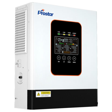
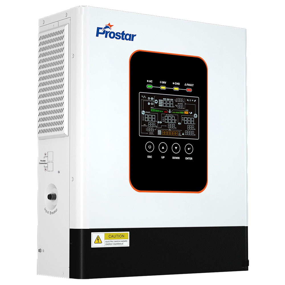
PIE5K-24L single phase pure sine wave hybrid inverter 5kw 24v
Hybrid Solar Inverter | 5000W | 24VDC | MPPT 40 - 450VDC | PV 9000W | Max. Charge 160A
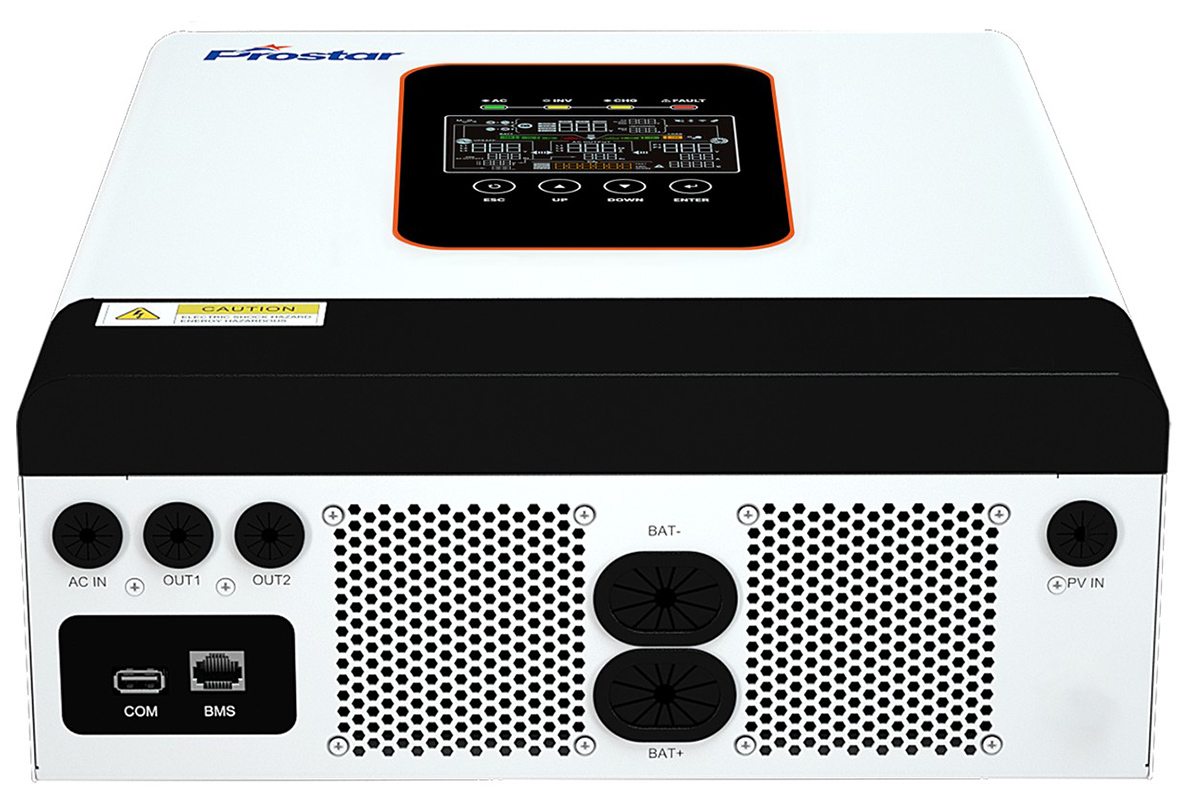
Prostar PIE5K-24L single phase pure sine wave hybrid inverter 5kw 24v is designed for residential solar power systems. It supports up to 9,000W PV input, a 60–450VDC MPPT range, and 160A maximum charging current. With grid-tie functionality, multiple battery compatibility, and 10kVA surge capacity, it provides flexible solar energy conversion and backup power management. Rated at 5,000VA/5,000W, this inverter operates with a 24VDC battery system and supports 208V, 220V, 230V, and 240V AC output. Its pure sine wave output makes it suitable for household appliances, electronic equipment, and other residential electrical loads. As hybrid inverter 5kw, Prostar PIE5K-24L combines photovoltaic input, AC charging, battery management, and grid-tie functionality in one compact unit.
Key Features and Technical Advantages
5,000W Rated Output with 10kVA Surge Capacity
The PIE5K-24L delivers 5,000VA/5,000W rated output power with a maximum surge capacity of 10kVA. The inverter provides additional power capacity for temporary startup currents from electrical appliances and equipment.
Its overload capacity is specified as:
| Load Condition | Permitted Duration |
|---|---|
| 102%–120% rated load | 1 minute |
| 120%–200% rated load | 10 seconds |
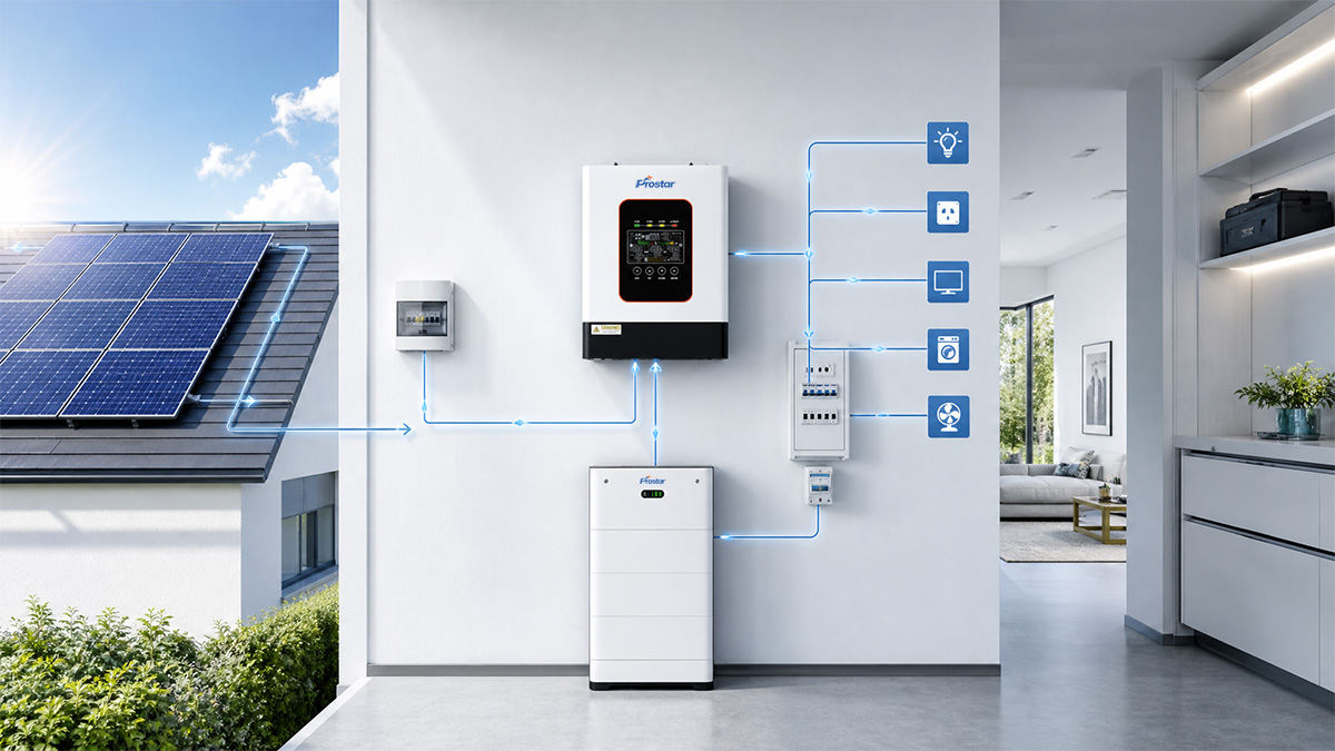
This 5kW hybrid inverter can supply power to multiple residential loads, including:
- Refrigerators and freezers.
- Air conditioners.
- Water pumps.
- Washing machines.
- Computers and networking equipment.
- Lighting and household electronics.
The 10kVA surge rating provides additional capacity for short-duration load peaks. However, actual motor-starting capability depends on the motor characteristics, starting method, power factor, and surge duration.
9,000W Maximum PV Input for Larger Solar Arrays
The PIE5K-24L supports a maximum PV array power of 9,000W. Its photovoltaic input specifications are:
| PV Input Parameter | Specification |
|---|---|
| Maximum PV Array Power | 9,000W |
| Maximum PV Input Current | 27A |
| Maximum PV Open Circuit Voltage | 500VDC |
| MPPT Operating Voltage | 60–450VDC |
| MPPT Trackers | 1 |
| Strings per MPPT | 1 |
The 9kW PV input capacity allows the connected solar array to be larger than the inverter’s 5kW rated AC output. This provides greater flexibility when designing residential solar installations. A larger PV array can also help maintain useful solar generation during periods of reduced sunlight, subject to site conditions and system design. Homeowners can increase their potential solar energy production and improve the utilization of available rooftop space. For installers, the wide MPPT voltage range provides flexibility when configuring PV modules in series. Important installation consideration: The PV string must comply with the inverter’s 500VDC maximum open-circuit voltage and 27A maximum input current. The 9,000W PV rating does not override these electrical limits.
Wide 60–450VDC MPPT Operating Range
The inverter features a wide MPPT operating voltage range from 60VDC to 450VDC. It uses one MPPT tracker with one PV string input. The wide operating range accommodates different photovoltaic string voltage configurations. The MPPT controller continuously adjusts the operating point to extract available solar power under changing irradiance and temperature conditions. The system can make better use of available photovoltaic energy throughout the day. For residential installers, the wide voltage range also provides greater flexibility in selecting compatible solar modules.
160A Maximum Charging Current for Faster Battery Charging
The PIE5K-24L supports a maximum charging current of 160A for PV, AC, and hybrid charging.
| Charging Parameter | Maximum Current |
|---|---|
| PV Charging | 160A |
| AC Charging | 160A |
| Hybrid Charging | 160A |
The high charging-current capability allows the inverter to replenish a 24V battery bank using available solar energy or AC power. Hybrid charging provides additional flexibility when both PV and AC charging sources are available. Users can reduce battery recharge time and maintain backup energy availability for nighttime operation or utility power interruptions. This makes the PIE5K-24L suitable for residential solar systems requiring relatively high battery charging capacity.
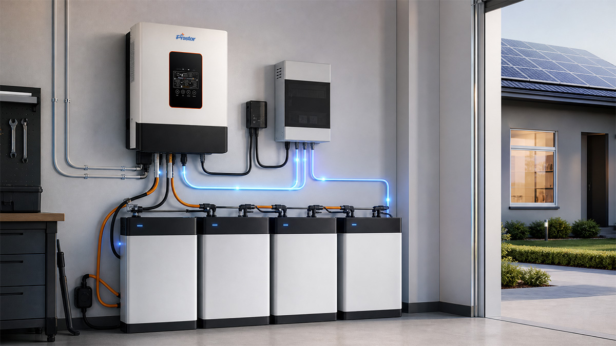
Multiple Battery Compatibility: Lead-Acid, Lithium-Ion, and User-Defined
The inverter supports three battery configuration options:
- Lead-acid batteries.
- Lithium-ion batteries.
- User-defined battery settings.
The nominal battery voltage is 24VDC. Specified battery charging parameters include:
| Battery Parameter | Specification |
|---|---|
| Nominal Battery Voltage | 24VDC |
| Floating Charge Voltage | 27VDC |
| Overcharge Protection | 30.5VDC |
| Charging Algorithms | 2-stage / 3-stage / PV charging |
Different battery chemistries can be accommodated through selectable charging algorithms and configurable parameters. For lithium battery installations, the RS485 BMS communication interface supports battery management system communication. Installers can select battery configurations according to project requirements, budget, and backup duration. The flexibility also makes this hybrid inverter 5kw suitable for different residential energy storage configurations. Technical note: Lithium battery compatibility must be confirmed against the battery manufacturer’s voltage limits, charging profile, BMS communication protocol, and maximum permitted charge/discharge current.
Pure Sine Wave Output
The PIE5K-24L provides pure sine wave AC output with total harmonic distortion (THD) of ≤3% under linear load conditions. A low-distortion sinusoidal waveform provides an AC power supply closer to conventional utility electricity. The output voltage supports multiple configurations:
| AC Output Parameter | Specification |
|---|---|
| Rated Output Power | 5,000W |
| Nominal Voltage | 208/220/230/240VAC |
| Voltage Regulation | ±5% |
| Waveform | Pure Sine Wave |
| THD | ≤3% (Linear Load) |
| Battery Mode Frequency | 50/60Hz ±0.1% |
The inverter can supply clean AC power to residential electronics, computers, communication equipment, and household appliances. It is suitable for applications where output waveform quality matters.
Grid-Tie Function for Flexible Energy Management
The PIE5K-24L supports grid-tie functionality and accepts utility or generator AC input. Its AC input specifications include:
| Parameter | Specification |
|---|---|
| Nominal Input Voltage | 208/220/230/240VAC |
| UPS Mode Voltage Range | 170–264VAC |
| APL/GEN Mode Voltage Range | 90–280VAC |
| Nominal Frequency | 50/60Hz |
| Frequency Operating Range | 40–70Hz |
| Power Factor | ≥0.99 |
The grid-tie function allows the inverter to integrate with grid-connected residential solar systems. Its wide AC input voltage range also provides flexibility in areas where utility voltage fluctuates or generator power is used. Homeowners can configure solar, battery, and grid energy sources according to their installation requirements. This helps reduce dependence on utility electricity when sufficient solar energy is available. The actual grid-export capability, anti-islanding protection, and applicable grid certification must be confirmed for the target market and inverter configuration.
Multiple Communication Interfaces and Remote Monitoring
The inverter is equipped with a 4.8-inch LCD and LED indicators.
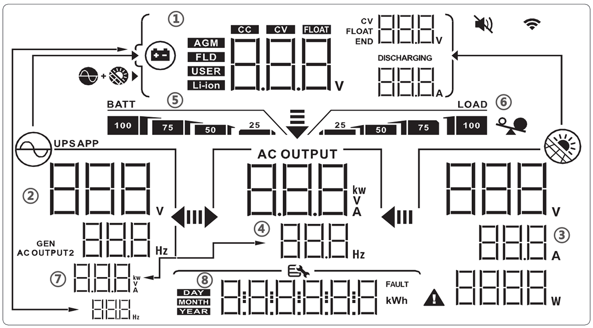
Available communication and monitoring interfaces include:
| Interface | Function |
|---|---|
| USB (COM) | Local communication |
| RS485 (BMS) | Lithium battery communication |
| Wi-Fi Module | Optional remote monitoring |
| GPRS | Optional remote monitoring |
| Ethernet | Optional network monitoring |
| CT Sensor/Meter | Optional system measurement |
The LCD provides local access to operating information and configuration settings. RS485 communication supports integration with compatible lithium battery BMS systems. Optional network modules provide additional monitoring possibilities. Installers can check system operating conditions more conveniently, while homeowners can monitor solar energy system performance remotely when the optional communication hardware is installed.
Inverter BMS Pin Definition and Connection Guide
Inverter BMS Port Pin Assignment
The BMS port on the inverter uses an RJ45 connector and is designed to connect Pin-to-Pin with compatible lithium batteries. The standard pinout assignment is as follows:
| Pin Number | BMS Port Definition |
| 1 | RS485B |
| 2 | RS485A |
| 3 | — (Reserved / Not Used) |
| 4 | CANH |
| 5 | CANL |
| 6 | — (Reserved / Not Used) |
| 7 | — (Reserved / Not Used) |
| 8 | — (Reserved / Not Used) |
How to Connect the Lithium Battery BMS
Follow these sequential steps to connect and configure the lithium battery BMS to the inverter:
Connect Power Cables
Ensure the DC power cables (BAT+ and BAT-) are securely connected between the lithium battery bank and the inverter’s power terminals following proper polarity.
Connect Communication Cable
Take a standard network cable (RJ45 battery communication cable). Plug one end into the BMS port of the inverter and the other end into the BMS communication port on the lithium battery.
Configure Battery Type (Program 17)
Turn on the system and access the inverter’s LCD setting menu. Set the battery type to ‘LIb’ or ‘FEL’ (Lithium / LiFePO4).
Enable BMS Communication Function (Program 44)
Go to Program 44 on the LCD menu and change the setting from OFF to the specific protocol matching your battery brand (e.g., PYL for Pylontech, GRO for Growatt, VOL for Voltronic, PAC for Pace, etc.)
Set BMS ID (Program 45)
Leave the BMS ID setting to auto (AtO) by default, which allows the system to poll and lock onto the correct battery ID automatically.
Once successfully connected and enabled, check the LCD display monitoring pages (such as voltage, current, and SOC) to ensure real-time data from the battery BMS is actively displaying without showing an ERR or Alarm 56 communication fault.
Applications
Off-Grid Solar Power Systems
For remote homes and locations with limited grid access, the inverter can convert PV and battery DC power into AC electricity. Its 160A maximum charging rating supports high-current battery charging when sufficient PV or AC input power is available. System designers should calculate the required battery capacity according to daily energy consumption and backup duration.
Hybrid Solar Backup Systems
In areas with unstable utility electricity, the PIE5K-24L can be configured to work with solar panels, batteries, and grid or generator input. Its specified transfer time of 10ms for personal computers and 20ms for household appliances helps reduce interruptions during applicable source transitions. This makes it suitable for residential backup applications requiring both solar energy utilization and battery-supported power.
Small Commercial and Home Office Applications
The 5kW output capacity can support selected small office loads, including:
- Desktop computers.
- Network switches and routers.
- Office lighting.
- Security systems.
- Small electronic equipment.
For commercial applications, the load profile and required backup time should be evaluated before system selection.
Important Engineering Considerations Before Installation
Selecting a hybrid inverter 5kw requires more than checking the rated output power. Installers should verify the PV configuration, battery discharge capacity, AC input requirements, and local electrical regulations.
PV String Design
The PIE5K-24L has a maximum PV open-circuit voltage of 500VDC. The PV string voltage must remain below this limit under the lowest expected operating temperature, because PV module open-circuit voltage increases as temperature decreases. Designers should also verify:
- Maximum PV input current: 27A.
- MPPT voltage range: 60–450VDC.
- Maximum PV array power: 9,000W.
- One MPPT tracker and one string input.
Battery Current and Capacity
A 5kW inverter operating from a 24V battery system requires substantial DC current. For illustration, assuming 93.5% DC-to-AC conversion efficiency:
IDC = PAC / (VDC * η) At 5,000W output and 24VDC: IDC = 5000W /(24V * 0.935) = 222.82A Suggest to choosing 2 * 25.6V 314Ah with 157A * 2 (314A) discharge current The battery bank, BMS, cables, DC protection devices, and connections must be appropriately rated for the actual operating current. The battery’s nominal 24V rating alone does not guarantee that it can supply the inverter’s full 5kW output.
Battery Charging Configuration
Different battery chemistries require different charging parameters. Before commissioning, installers should configure:
- Battery type.
- Bulk/absorption charging voltage, where applicable.
- Float charging voltage.
- Maximum charging current.
- Lithium BMS communication, where supported.
The specified 27V floating voltage and 30.5V overcharge protection threshold should be checked against the selected battery manufacturer’s requirements.
Grid Connection and Compliance
Grid-connected installations must comply with the applicable national and local electrical regulations. Relevant standards and regulatory frameworks may include:
- IEC 62109-1 and IEC 62109-2 for safety requirements of power converters used in photovoltaic systems.
- IEC 62116 for anti-islanding test procedures.
- Local grid interconnection and electrical installation codes.
These are relevant standards for evaluating solar inverter systems. Their mention does not establish that the PIE5K-24L has been tested or certified to them.
Frequently Asked Questions (FAQ)
What is the transfer time for backup switching?
What is the maximum PV input power of the PIE5K-24L 5kW hybrid solar inverter?
How does this pure sine wave off grid inverter handle heavy surge loads?
Is remote monitoring supported?
Does the PIE5K-24L support grid-tie and generator input?
The Articles You may Like
- What is the CT Sensor in Solar Inverter On Off Grid
- Hybrid Solar Inverters Provide Off-grid Power Availability
- Which Transformer is Good for Home Solar Inverter
- Can Off Grid Solar Inverter Charge Controller Run without Battery
- How to Use Off Grid Solar Inverter Without Battery
- Hybrid power – wikipedia
| Model | PIE5K-24L |
| PHASE | Single phase, L+N+PE |
| RATED POWER | 5000VA/5000W |
| Parallel Capability | No |
| Grid-tie Function | Supported |
| Installation | Wall-mounted |
| Dimension W x H x D (mm) | 410x336x125 |
| Net Weight (Kg) | 8.1 |
| PV INPUT | |
| Max. PV Array Power | 9000W |
| Max. PV Input Current | 27A |
| Max. PV Open Circuit Voltage | 500VDC |
| MPPT Operating Voltage Range | 60 – 450VDC |
| Max. PV Charge Current | 160A |
| Max. AC Charge Current | 160A |
| Max. Hybrid Charge Current | 160A |
| Number of MPPT Trackers / Strings per MPPT | 1 / 1 |
| GRID / GENERATOR | |
| Nominal Input Voltage | 208VAC/220VAC/230VAC/240VAC |
| Selectable Voltage Range | 170-264 VAC (UPS mode); 90-280 VAC (APL/GEN mode) |
| Nominal Frequency Range | 50 Hz / 60 Hz (Auto-Sensing, 40 Hz – 70 Hz) |
| Power Factor | ≥0.99 |
| AC OUTPUT | |
| Nominal AC Output Voltage | 208VAC/220VAC/230VAC/240VAC ± 5% |
| Output Frequency Range | Grid Mode: Synchronized to Grid; Battery Mode: 50 Hz /60Hz ±0.1% |
| Surge Power | 10kVA |
| THD | ≤3% (Linear Load) |
| Transfer Time | 10ms (For Personal Computers); 20ms (For Home Appliances) |
| Waveform | Pure sine wave |
| Max. Efficiency (DC to AC) | 93.5% |
| Overload Capacity | 1min @102%~120% Load 10s @120%~200% Load |
| BATTERY | |
| Compatible Battery Types | Lead-acid / Lithium-ion / User-Defined |
| Nominal Battery Voltage | 24VDC |
| Floating Charge Voltage | 27VDC |
| Overcharge Protection | 30.5VDC |
| Charging Algorithm | Two stages(CC/Float) / Three stages(CC/CV/Float) / PV Charging [settable] |
| INTERFACE | |
| Display | 4.8-inch LCD + LED |
| Communication Interface | USB(COM), RS485(BMS), CT Sensor/Meter optional |
| Remote Monitor | Wi-Fi Module / GPRS / Ethernet (Optional) |
| ENVIRONMENT | |
| Humidity | 5% to 95% Relative Humidity(Non-condensing) |
| Operating Temperature | -10°C to 60°C |
| Storage Temperature | -15°C to 60°C |
| Noise Level | < 45 dB @ 1 meter |
| Cooling | Intelligent Fan Cooling |
| IP Rating | IP21 |
Download CATALOG